RTFTWalk Routines
Note: Some portions of the text below were taken from Walter Ogburn's thesis and a writeup for the c58 analysis by Scott Hertel.
Overview
Although the rtftWalk routines can be applied to both charge and phonon traces, due to better signal to noise and a stronger need to analyze the risetime of the phonon pulses, this routine is primarily only used on phonon pulses. The original algorithm, with fixed frequency low-pass filtering, was ported from Darkpipe. It exists in BatRoot as the analysis class ConstFreqRTFTWalk. A bug related to the fall-time calculation was fixed on the intial import to BatRoot, but since then some modification of the filtering frequency has been implemented.
In all versions of the walk routines, the pulses are first smoothed with a second-order Butterworth low-pass filter. The algorithm then finds the highest point of the filtered pulse, which is defined as the 100% point. It then walks down the rising edge to find the rise time points of interest and similarly down the falling edge for fall time points. For each point of interest, it walks down the slope until it encounters the first sample that is below the desired threshold and then interpolates between the samples just above and just below the threshold. This interpolation gives an estimate of timing with resolution finer than the digitizer sample time. The default points of interest are at every 10% along the rising edges and at 80%, 40% and 20% on the falling edges. This choice in points can be easily modified.
Because the pulse is expected to lie within a specific time window about the trigger time, the walk times are restricted to occur after a preset bin based on the pre-trigger time. This limit (PEAK_WINDOW_MIN) is specified in the analysis configuration file along with a number of other parameters related to the pre-walk filtering (see list below). Additionally, to avoid edge effects associated with filtering a finite trace, the search for the maximum adc bin is restricted to lie between PEAK_WINDOW_MIN and the bin that is the value of the total trace length minus RTFT_PULLBACK.
At the moment, there are three walk routines in BatRoot:
- ConstFreqRTFTWalk - original routine ported from Darkpipe. This algorithm first filters phonon traces with a low-pass 2nd order butterworth filter. All phonon traces are filtered with the same cutoff frequency (currently 50 kHz for Ge).
- VarFreqRTFTWalk - modified walk routine. This algorithm also filters phonon traces with a low-pass 2nd order butterworth filter. The cutoff frequency for a given phonon pulse varies depending on its amplitude (small pulses have a lower cutoff frequency and large pulses have an upper cutoff frequency).
- RTFTWalkCharge - constant frequency filtering of charge pulses, rarely used
Parameters in the Analysis Settings File that are Relevant to RTFTWalk:
- P_RTFT_BUTTERWORTH_ORDER: Order of the rolloff for the butterworth filter applied to phonon traces.
- P_RTFT_BUTTERWORTH_CUTOFF_DEFAULT: Frequency cutoff for ConstFreqRTFTWalk.
- P_RTFT_BUTTERWORTH_CUTOFF_LOWER(UPPER)LIMIT: Minimum and maximum frequency cutoff for the VarFreqRTFTWalk.
- P_RTFT_BUTTERWORTH_1: parameter 1 for VarFreqRTFTWalk frequency cutoff functional form (parameter B in the discussion below)
- P_RTFT_BUTTERWORTH_2: parameter 2 for VarFreqRTFTWalk frequency cutoff functional form (parameter “multiplier” in the discussion below)
- P_RTFT_BUTTERWORTH_SCALEFACTOR: The scalefactor in the frequency cutoff function form (parameter A in the discussion below)
- Q_RTFT_BUTTERWORTH_ORDER: Order of the rolloff for the butterworth filter applied to charge traces.
- Q_RTFT_BUTTERWORTH_CUTOFF: Frequency cutoff for charge traces (as implemented in RTFTWalkCharge)
- RTFT_PULLBACK: number of bins that are discarded at the end of the trace in the search for the pulse maximum. This is done to avoid edge effects associated with filtering a finite trace.
Details Specific to the ConstFreqRTFTWalk
As mentioned above, the ConstFreqRTFTWalk routine only differs from VarFreqRTFTWalk in that the pre-walk filtering cutoff frequency is fixed to the same value for all phonon pulses. Since analysis of R123, this cutoff has been 50 kHz for Ge ZIP detectors. For Si detectors the optimal cutoff was found to be 90 kHz.
Prior to analysis of R123, a smaller cutoff of 22.5 kHz was used on Ge detectors. The figure below shows an example of a phonon pulse before and after applying the pre-walk filter (filtering cutoff is 22.5 kHz here). The change from the lower to the higher cutoff frequency was made when it was found that the lower cutoff significantly biased the risetime to longer times and the delay to shorter times. During R118/119 analysis, optimization of this cutoff was performed on ZIPs and 50 kHz was chosen as the optimal cutoff. An optimization study was also performed on iZIPs. The conclusion of the iZIP study was that the filter cutoff should be kept above 35 kHz to avoid compromising risetime information, so for simplicity we have kept the iZIP cutoff the same as the ZIP value. These studies are linked in the reference list at the bottom.
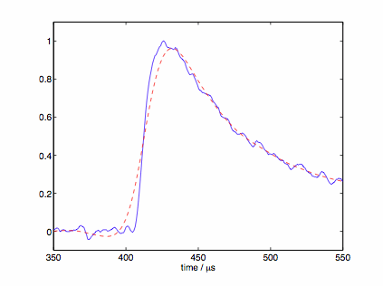
Figure 1: Phonon pulse before (blue) and after (red) filtering with 22.5 kHz, 2nd order butterworth filter.
Details Specific to the VarFreqRTFTWalk
The following is an excerpt from Scott's c58 writeup on the variable frequency RTFTwalk. See this link for the full discussion.
It was found in the analysis of the Soudan runs 123 and 124 that small, slow traces (defined by looking at the non-primary channel for low-energy events) have FALSELY SLOW rising edge rtftWalk times.
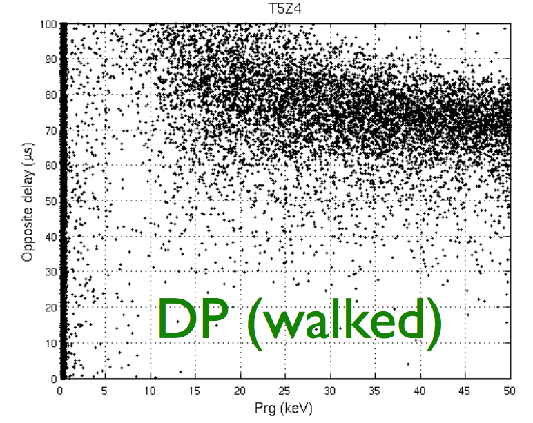
Figure 2: The 20% risetime in the quadrant opposite to the primary, as a function of energy. At low energies, the signal-to-noise is so poor, that the jitter on the rising edge pushes the delays towards the peak.
It is quite easy to see where this pathology originates: the rtftWalk routine finds the crossing of a threshold closest to the peak. For a slow, low signal-to-noise trace, the rising edge is not monotonic. The crossing closest to the peak will show the affects of random jitter, by being artificially pushed towards the peak. Most troublesome, this is an inherently noisy push; one that can not be merely subtracted out. The hope in c58 was that the pathological effects walking along a jittery rising edge could somehow be mediated, thus resulting in both better position correction and better end discrimination.
Figure 3: A not unusual pulse, as put through the rtftWalk routine (left and right are zoomed out and zoomed in versions of the same pulse). On top is the charge trace, followed by channels A, B, C, and D. The raw trace is in black, the trace after application of a 50kHz butterworth filter is in blue, and the 20% crossing time (as found by rtftWalk) is shown in red.
Varying the pre-Walk Filter
Rather than change the walking method, the goal was to smooth the rising edge of the trace in such a way that is becomes monotonic, but in a way that loses no useful timing information.
A correlation between “optimal butterworth cutoff” was found (for each channel of each detector, using c34 data) using a simple two-parameter power law fit.
Butterworth Cutoff = mulitplier * A * Q^B
(where Q is the signal to noise ratio).
For implementation into BatRoot, the butterworth filter cutoff is constructed from quantities already calculated by other functions. This reduced the necessary computation time. Peak height was derived from the phonon optimal filter (optimal filter template height)*(PXOFamps) and the noise level defined as PXstd/PXnorm, giving a signal-to-noise parameter Q of
Q = (optimal filter template height * PXOFamps ) / ( PXstd / PXnorm )
The cutoff functions (as functions of this Q) must be pre-calculated from calibration data.
A multiplier value of '1' was used to reconstruct the R125-R128 dataset, and must be optimized for new detectors.
Further Development
Studies of the use of the variable frequency walk for iZIPs have not be performed yet.
The idea for reducing the noise in the walked timing quantities for low-energy pulses showed significant promise early on in CDMSII detectors, and perhaps contributed significantly to the position correction of low energy events. Considerable freedom exists in the cutoff function in the form of the A parameter. Initial studies indicated that tuning A is an exercise in optimizing tradeoff between minimizing energy dependence and maximizing surface event discrimination (for CDMSII detectors). Optimization of the A parameter is still not well-understood and would need to be further studied in subsequent implementation of this routine.