- Site Intro
- Sector Pair
- Subbooster System
- Klystron System
- Camac System
- Definitions
- References
- Acknowledgements
Subbooster System Diagram
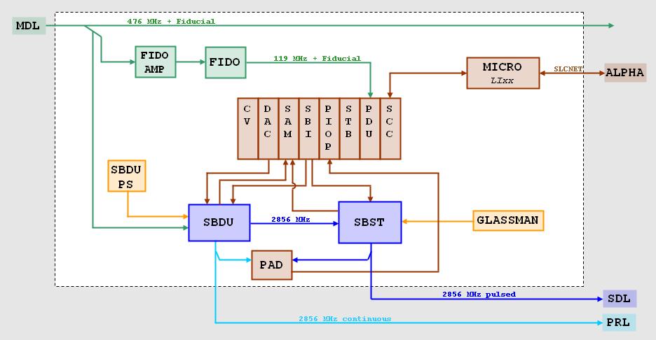
Notes:
This diagram shows the standard hardware associated with every sector subbooster. The subbooster is located at the very beginning of every sector, facing upstream. The subbooster contains an internal modulator and klystron, which are housed inside the closed subbooster cabinet. The subbooster drive unit (SBDU), its associated power supply, the Glassman HV power supply for the subbooster's modulator, and the PAD for measuring the phase of the subbooster's RF output are located in the rack connected to that cabinet on the right-hand side. The CAMAC crate that contains the subbooster interface (SBI) and the subbooster PIOP is sector crate 2, located in rack 2A at klystron station 2. The FIDO chassis and its associated amplifier are located in rack 1A for klystron 1, just behind the subbooster cabinet.
The 476 MHz main drive line (MDL) signal (with fiducial) is picked off above the subboster and split by a coupler to send outputs to both the SBDU and FIDO. The FIDO converts the signal to the 119 MHz timing signal with fiducial, that feeds every PDU. The PDU then sends the necessary triggers to each module controlling a triggered device (e.g. the SBI for the subbooster) on the upper backplane of the CAMAC crate.
The SBDU phase-shifts and attenuates the MDL signal as needed, multiplies it by four to get 2856 MHz, and amplifies the signal. It then generates the phase-reference line (PRL) for the sector, and provides the drive signal to the subbooster's internal klystron. Both the SBDU and the subbooster modulator are triggered by the SBI, allowing the subbooster to generate a pulsed 2856 MHz RF output that travels on the sub-drive line (SDL) to drive the eight klystrons in that sector.
Every sector has a microprocessor computer (micro) in its I&C alcove that interfaces between the Alpha central host computer, on which the SCP runs, and the typical CAMAC crates in that sector (see the CAMAC page). Linac sector micros have the database name LIxx, where "xx" is the number of the sector (00-30). The line of communication between the Alpha and the micros is called SLCNET. Every CAMAC crate has a serial crate controller (SCC) module, through which information is passed to and from the micro.