- Site Intro
- Sector Pair
- Subbooster System
- Klystron System
- Camac System
- Definitions
- References
- Acknowledgements
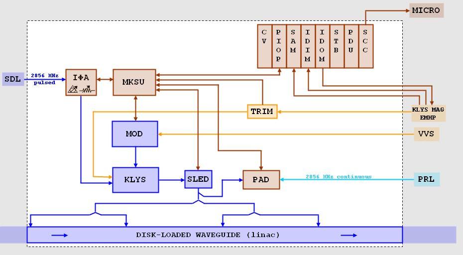
Klystron System Diagram
Notes:
The Klystron System shown here contains all of the basic hardware that is associated with every "regular" klystron station in the linac. The eight klystrons in a linac sector are spaced 40 feet apart down the length of the sector in the klystron gallery. The modulator cabinet is located just behind the klystron, along with two side-by-side racks (labeled A and B) that hold various controls and power supply components. Click on any item in the diagram for a description of its functions and location.
The klystron gets its voltage pulse from its associated modulator, and its 2856 MHz drive pulse from the subbooster, via the sub-drive line (SDL) that serves all eight klystrons in the sector. An I-Phi-A chassis, located in rack B at each klystron station, phase-shifts and attenuates the SDL signal for that individual klystron. A PAD in that same rack is used to measure phase and amplitude of the klystron's RF output to the linac. These measurements are made with respect to the phase reference line (PRL), generated by the sector SBDU. The modulator, klystron, SLED cavity, I-Phi-A, and PAD are monitored, controlled, and triggered by the modulator-klystron support unit (MKSU) chassis in rack B. A dedicated PIOP module for each MKSU interfaces that klystron system with the control system.
The CAMAC modules shown in this diagram are somewhat misleading, because there is not a CAMAC crate at every klystron station; the typical sector has crates only at stations 2, 5, and 8. The PIOPs for klystron stations 1-3 are in CAMAC crate 2, in rack 2A. The PIOPs for stations 4-6 are in crate 3 (rack 5A), and the PIOPs for klystrons 7 and 8 are in crate 4 (rack 8A). See the CAMAC page for more details about typical sector crates.
The klystron magnet EMHP is a bulk power supply located in each odd sector, that provides high-voltage DC current to the solenoid focusing magnets inside each klystron for two consecutive sectors. SAM, IDIM, and IDOM modules used for control and readback functions for the EMHP are located in crate 1 in the odd sector's I&C alcove. However, these modules have multiple channels that are used for a variety of hardware, some that apply to a single sector and some to a pair of sectors, so they can't easily be put into the Sector Pair diagram either; and so they are shown here simply to indicate their relationship to the klystron system. At every klystron station, the EMHP current can be adjusted for that individual focusing magnet by a trim chassis, a variable power supply located at the bottom of rack A. The trim supply is monitored and can be controlled (maybe!) via the MKSU.
The klystron's pulsed, high-power, 2856 MHz RF output is generated by the modulator's triggered voltage pulse and the subbooster's concurrent drive pulse. It passes through a SLED cavity that stores up the energy and is dumped at a triggered time into the waveguide that carries it to the accelerator. Just after SLED, the klystron output is split two ways, and goes down into the tunnel housing through two penetrations in the gallery floor. In the tunnel, each of these is then split in half again, for a total of four equal signals, input to the accelerator disk-loaded waveguide at 10-foot increments. For more on how a klystron works, see the Basics page (later).