IQ&A Module Calibration Procedure


Background:

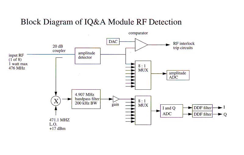
Each of the 8 RF measurement channels in an IQ&A detector module contains and amplitude detector for RF interlocks and a digital IQ demodulation circuit for measuring the in-phase (I) and quadrature (Q) components of the RF vector.  From the IQ components the amplitude and phase can be easily calculated.  A basic signal flow diagram for a single channel is shown below (Note that the frequencies in this diagram are the PEP-II frequencies.  The SPEAR3 Input RF frequency is 476.3 MHz, the LO is 471.2 MHz, and the BPF is centered around 5.122 MHz):

To accurately determine the amplitude if the RF signal each channel of the IQ&A module must be calibrated by applying a known amount of RF power and running an EPICS based procedure which measures the sensitivity (or gain) of the channel.  The procedure to complete this calibration is as follows:

Calibration Procedure:

  1. IQ&A module should be installed in the VXI crate.  The 471.2 MHz LO should be connected.  The LO cable is a SMA cable sourced at the clock module and is labeled to correspond to the IQ&A module and slot being calibrated.  It is important that the correct LO cable is used since the phase length of this cable will directly affect the measured RF phase.
  2. The VXI crate should be powered up for at least 30 minutes before the calibration is performed.  This allows sufficient time for the oven in the IQ&A module to come up to operating temperature.
  3. The individual SMA cables for IQ&A channels 1-8 should be disconnected prior to calibration to prevent errors due to cross talk.
  4. All VXI interlock should be made up before calibration.  This is necessary because the IQ&A module will not measure the signal amplitude if there is a VXI fault present (unfortunate bug).  To confirm that there is no VXI fault one can look at either the "VXI fault" LED on the arc interlock module (AIM) located in VXI slot 12, the "VXI fault" LED on the local panel or on the EPICS panel for the AIM module.  If a station Reset does not clear the fault there may be Allen Bradley interlock not complete (for example the klystron filaments being off).  The user should place the station in "Offline" mode by selecting OFFLINE on the main EPICS panel for the station.  A station reset should then clear the VXI fault.
  5. Locate the SMA cable normally connected to IQ&A module in slot 7 channel 6.  This is a copy of the station reference 476.3 MHz reference which is normally monitored by the IQ&A module but we will temporarily use it to provide the RF power needed for the calibration.  In order to calibrate the IQ&A module with a power comparable to that normally incident to the module, we amplify this signal with a known amplifier. There is a coupled output, down 19.45 dB, that can be monitored with a calibrated power meter.  Normally the power into the IQ&A module should be 280 +/- 5 mW.
  6. Bring up the main EPICS panel for the station and then proceed to the Power/Phases panel.  This panel shows what RF signals are connected to which IQ&A modules and channels.  Find the power (or amplitude) display box for channel 1 of the IQ&A module to be calibrated and activate the portion of this box labeled DB (for database) using the left mouse button.  This will bring up another display window with details for that particular channel.
  7. On the bottom right of this new display there is a place to enter the amount of RF power we will be calibrating the channel with, it is simply labeled "Power (mW)".  Place the cursor into this box, click with the left button, enter the amount of mW (for example 32.3) measured with the trusted RF power meter and finish with a carriage return.  The value should be visible in this dialog box even when the mouse moves the cursor away.  If not re-type in the RF power value and remember to finish with a carriage return.
  8. Connect the RF reference power SMA cable to channel 1.  The connection should be snug but do not over tighten!
  9. With the left mouse button activate the calibration procedure by activating the "Calibrate" button on the lower right portion of the EPICS "DB" panel.
  10. The procedure will recalculate the conversion loss for both the amplitude detector and the IQ detector and write the new values into the dialog boxes on the lower left of the EPICS "DB" display.  This will take a few seconds.  The user should observe these values and make sure they are acceptable before moving on to the next channel.  Acceptable values are:
 
Title
Minimum Acceptable Value
Maximum Acceptable Value
Amplitude Conversion Loss
12 dB
14 dB
IQ Conversion Loss
21 dB
23 dB
 
  1. If the channel is not within the specified values, the module should be replaced.  Some discretion should be applied here though.  If the module is slightly out of tolerance (2 dB from spec) is would be OK to continue to operate this unit but it should be repaired when it is convenient to do so.  Also note that the amplitude channel provides the interlocking function, if this conversion factor is OK the RF interlocks will continue to operate correctly.
  2. If the channel is OK, move the RF reference to the next channel, close the old EPICS "DB" display and open the "DB" display for the next channel.  You will note the EPICS has remembered your reference power setting from the last channel and it is not necessary to retype the RF power level.  Simply connect the RF power to the new channel and activate the calibrate button.
  3. Continue to operate the calibration on each channel until the IQ&A module(s) calibration is complete.
  4. Reconnect the SMA cables to the IQ&A channel labeled on the cable tag.  If any of the tags are getting worn or ready to fall off, take time to repair the tag or order new ones of necessary.
  5. Return the station to Online Mode (if it was Online when you began the calibration).
  6. IQ&A module calibration is complete.

Equations using I/Q or A:

The EPICS IOC calculates phase and power from I and Q at 2 hz. When the station state is ON_FM, the phase and power is calculated from the diode amplitude at a slower rate since, unlike the I and Q measurements, only one channel can be read at a time.
  1. The equations used in calculating power or amplitude and phase from IQ:
    Raw In-Phase (counts) = Ir
    Raw Quadrature (counts) = Qr
    Scaled In-Phase (V) = Is
    Scaled Quadrature (V) = Qs
    Corrected In-Phase (V) = Ic
    Corrected Quadrature (V) = Qc
    Unsmoothed Amplitude (V) = Ac
    Smoothed Amplitude (V or kV) = Ampl
    Power (W or kW) = Power
    Phase (deg) = Phase
    Phase Offset (deg) = Offset
    IQ Conversion Loss = IQConvLoss
    IQ Other Loss = IQOtherLoss
    Scale Factor = Scale
    Conversion Factor = Conv (0.31623 for kW, 10 for W)
    Smoothing Factor = Smoo (0 = no smoothing)

    IQConvLoss = 10**(IQConvLossDB/20)
    Is = Ir * 2/65535 * IQConvLoss
    Qs = Ir * 2/65535 * IQConvLoss
    Ic = Is for identity directivity matrix
    Qc = Qs for identity directivity matrix
    Otherwise, Ic,Qc = directivity matrix * forward,reflected Is,Qs
    IQOtherLoss = 10**((CplgLossDB+CableLossDB+CorrLossDB)/20)
    Scale = IQOtherLoss/1000 (for kW) or IQOtherLoss (for W and kV)
    Ac = sqrt(Ic**2 + Qc**2) * Scale
    Ampl = (Ampl * Smoo) + (Ac * (1 - Smoo))
    Power = (Ampl/Conv)**2
    Phase = (atan2(Qc,Ic) * 180/pi) + Offset

  2. The equations used in calculating power or amplitude from the diode amplitude:
    Diode Amplitude (V) = Araw
    Scaled Amplitude (V) = As
    Smoothed Amplitude (V or kV) = Ampl
    Power (W or kW) = Power
    Amplitude Loss = AmplLoss
    Scale Factor = Scale
    Conversion Factor = Conv (0.31623 for kW, 10 for W)
    Smoothing Factor = Smoo (0 = no smoothing)

    AmplLoss = 10**(AmplConvLossDB+CplgLossDB+CableLossDB+CorrLossDB)/20
    Scale = AmplLoss/1000 (for kW) or AmplLoss (for W and kV)
    As = Araw * Scale
    Ampl = (Ampl * Smoo) + (As * (1 - Smoo))
    Power = (Ampl/Conv)**2

  3. The equations used in calculating diode threshhold from power or voltage limit:
    Power/Voltage Limit(W,kW,kV) = Limit
    Conversion Factor = Conv (0.31623 for kW, 10 for W)
    Amplitude Loss = AmplLoss
    Scale Factor = Scale
    Diode Threshhold (V) = Alimit

    AmplLoss = 10**(AmplConvLossDB+CplgLossDB+CableLossDB+CorrLossDB)/20
    Scale = AmplLoss/1000 (for kW) or AmplLoss (for W and kV)
    If power, Alimit = Conv * sqrt(Limit)/Scale
    If voltage, Alimit = Limit/Scale

  4. The equations used in calculating diode threshhold from voltage limit:
    Voltage Limit (kV) = Plimit
    Conversion Factor = Conv (0.31623 for kW, 10 for W)
    Amplitude Loss = AmplLoss
    Scale Factor = Scale
    Diode Threshhold (V) = Alimit

    AmplLoss = 10**(AmplConvLossDB+CplgLossDB+CableLossDB+CorrLossDB)/20
    Scale = AmplLoss/1000 (for kW) or AmplLoss (for W and kV)
    Alimit = Conv * sqrt(Plimit)/Scale

  5. The equations used in calculating IQ conversion loss from I and Q:
    Raw In-Phase (counts) = Ir
    Raw Quadrature (counts) = Qr
    Raw Amplitude (V) = Araw
    Calibration Power (mW) = Pcal
    IQ Conversion Loss (dB) = IQConvLossDB

    Araw = sqrt(Iraw**2 + Qraw**2) * 2/65535
    IQConvLossDB = 20 * log10(0.31623 * sqrt(Pcal)/Araw)

  6. The equations used in calculating Amplitude conversion loss from diode amplitude:
    Diode Amplitude (V) = Araw
    Calibration Power (mW) = Pcal
    Ampl Conversion Loss (dB) = AmplConvLossDB

    AmplConvLossDB = 20 * log10(0.31623 * sqrt(Pcal)/Araw)

Contact:  Stephanie Allison
Last Modified:  Thursday, Jul 11, 2008