Each PEP RF station contains 2 (2-Cavity Station) or 3 (4-Cavity Station) IQ&A modules. Each module measures 8 RF signals. The module performs two main tasks:
The IQA module also performs these additional tasks:
Inputs:
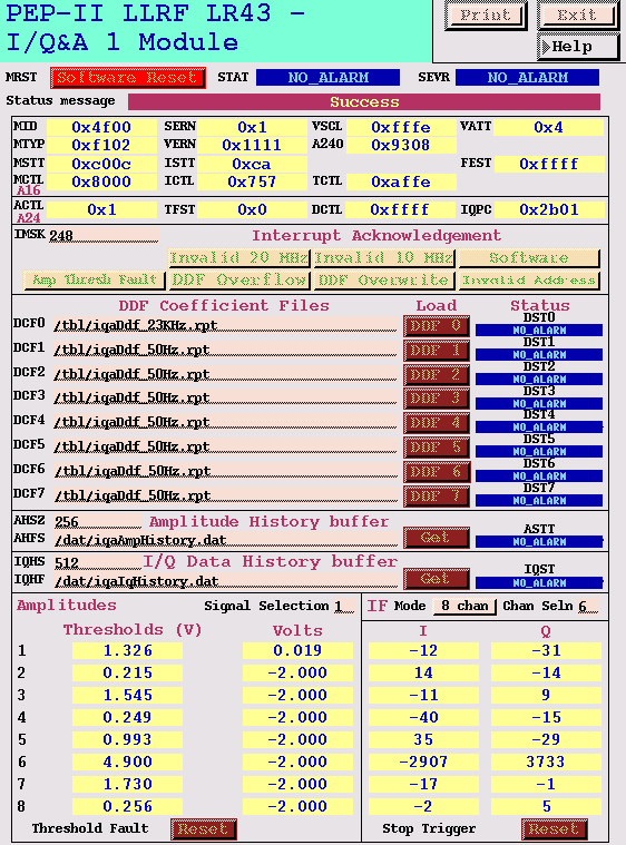
The speed of the trip circuit is set by 8 DIP switches (SW2) on the main circuit board. All channels are set for slow response (3 us) except for channel 2 of the IQ&A module in slot 7, this channel is protecting the klystron from reflected power and must be set to respond fast. The status of the SW2 setting is read by EPICS and displayed as entry "FEST" on the IQ&A module EPICS panel. Set SW2 for:
Slot 7: FEST = 0xFDFF
Slot 9 or 11: FEST = 0xFFFF
The bandwidth of the IQ detector is determined by a coefficient file. Presently all channels except for the klystron output channel are set for the lowest possible bandwidth (maximum filtering). The klystron output channel (IQ&A module in slot 7, channel #1) is setup with sufficient bandwidth to support the ripple loop. File details:
/tbl/iqaDdf_50Hz.rpt: Bandwidth = 5 Hz, Output Rate = 50 Hz
for all channels except klystron output/tbl/iqaDdf_23KHz.rpt: Bandwidth = 10 kHz, Output Rate = 23 kHz
for the klystron output channel (IQ&A slot 7 channel #1)
AHSZ - Amplitude history buffer size.
This field is set by the EPICS database. The normal value is 512 (k).AHFS - Amplitude history file name.
This field is set by the EPICS database. Something like "/dat/FAULTIqadAmp_dd", where the "d" represent integers that identify the IQ&A module and the fault file number.
IQHS - I/Q history buffer size.
This field is set by the EPICS database. The normal value is 512 (k).AHFS - I/Q history file name.
This field is set by the EPICS database. Something like "/dat/iqaIqHistory.dat"
On the lower right of the IQ&A EPICS panel there is a button for selecting the mode of the IQ processing. The IF mode should always be set to 8 chan(nel). The 1 chan(nel) mode is for test purposes and not supported by the EPICS database.
Determines what types of interrupts are passed to the VXI crate processor. The proper value for this field is 0xFFFFFFF8 (248).
These setpoints are set during IQ&A module calibration. The voltage steeping for each channel is determined in the EPICS database (Power/Phases panel then on to the Power Trip Limit panel). If the original steeping is unknown, the correct value can be restored by placing the cursor in the associated trip limit entry field on the Power Trip Limit panel and entering a carriage return. This will force the EPICS database to recalculate the trip voltage and restore the correct value.

Resets the module and reloads the DDF files and comparator trip points. The module will become unsynchronized with the RF reference after a Software Reset. It will be necessary to force a "resynch" on the clock module panel to restore the proper phase relationships. This is most important if the IQ&A module is in slot 7 since the klystron phase is measured in channel 1 and is directly tied to the phase margins of the direct RF feedback loop.
Clears the latched amplitude fault. This button is pushed by a station Reset and should not need to be activated from the IQ&A panel (except during testing in the lab).
Clears a latched stop trigger. This trigger stops the internal ADC from writing the IQ and Amplitude information to the long memories, holding the data until it can be read out to a file. This button is also pushed by a station Reset and should not need to be activated from the IQ&A panel (except during testing in the lab).

Contact: Stephanie Allison
Last Modified: Thursday, Jul 11, 2008