 PEP-II
I.R. Technical Information
Last update: 24 Oct 96
General Information

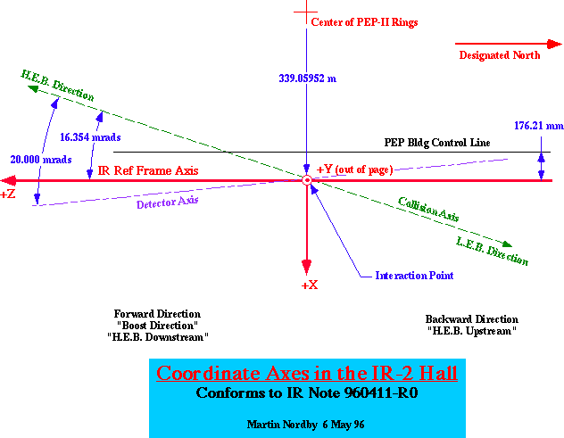
- Schematic of coordinate axes in the IR-2 Hall, and their relation
- Tabulated water requirements in the IR-2 straight section,
for Cu and Alum water systems. Includes HEB, LEB, and IR magnets
and vacuum system devices.
- Rev 2.1: Expanded to include valve locations and lenght
of hose runs for all devices (18 Oct 96)
IR Notes and Technical Spec's
- Notes to be used for drawings of parts and assemblies which
are exposed to the PEP-II ultra-high vacuum. These have been
used for drawings for the HER, and will continue to be used for
the I.R.
- Released: 23 Oct 96
-
- Explains IR coordinate systems in detail, including how they
relate to one another, and references for the information given.
Tabulated data, below, may reference any of these coordinate systems,
so be forewarned to check for the correct reference [MS Word 6,
html].
-
- Drawing number conventions for I.R.
-
- CAD file layout conventions for the I.R. This describes standard
views, coordinate systems, and layout orientations to be used
for I.R. CAD files.
IR-2 BSC and Magnet Position Data
All information originates from MAGBENDS output from Mike Sullivan.
Coordinates and positions are based on the IR Reference Frame
coordiante system (see IR Note, above, for an explanation of this).
This data agrees with MAD positions to <1 micron.
Magnet Positions for IR-2 Straight
- No Solenoid Compensation configuration
H.E.B. Beam Stay-Clears Through the IR
- No Solenoid Compensation configuration
L.E.B. Beam Stay-Clears Through the IR
- No Solenoid Compensation configuration
-
Luminosity Beam Stay-Clears Through the IR
- Shows positions and circular size of S.R. from the I.P. collision
-
- No Solenoid Compensation configuration
- (10/4/96: Updated to correct error in X-position column)
[I.R. Home Page]
[PEP-II]
[SLAC]
For comments / questions about the I.R. WWW pages,
contact nordby@slac.stanford.edu
 PEP-II
I.R. Technical Information
 PEP-II
I.R. Technical Information