SUMMARY OF THE 1994-95 RUN FOR THE DAMPING
RINGS
Patrick Krejcik
May 1995
The damping rings performed well over this 14 month run, beginning with a
smooth turn on in February 1995. The operation was marred by several hardware
failures, but there were also extended periods of trouble free running. The
major upgrade since the previous run was the installation of new low impedance
vacuum chambers, which proved to be trouble free and allowed for operation at
higher intensities than in previous years. The major hardware and reliability
issues are summarized in the next section, followed a performance review in
which the histories of key beam parameters are given. The performance is
divided into intensity related effects, for stable operation, and emittance
related issues.
This item remains a major concern for the damping rings since a large portion
of the SLC downtime is directly attributable to problems within the damping
ring complex. The major problems we experienced during the run are listed below.
Quite close to the beginning of the run on February 19th, after a successful
commissioning period, operations came to an abrupt halt with a fire alarm
reported in the NDR. The cooling water pump for the damping rings tripped as a
result of a scheduled power outage that interrupted the site compressed air.
The SDR magnets tripped off in rapid succession, but the NDR, NLTR and NRTL
failed to trip and remained on for up to 30 minutes without cooling before
being turned off by the operators. The overheating damaged the epoxy insulation
on the magnets, leaving in places a charred and molten residue. Miraculously,
most of the magnets were still operable and remained in use for the remainder
of the run. Several hundred cooling hoses were replaced as a result of steam
damage and a few wet coils that did not pass hi-pot testing were replaced.
The failure of the magnet protection interlock system was attributed to a
single reset switch being stuck in the override position. The failure was made
worse by the interlock architecture that funneled all of the north ring complex
supplies through a single chassis with one reset switch. In addition to fixing
the design problem with the switch, the single interlock chassis is being
replaced with an entirely new system consisting of individual interlock modules
for each power supply.
Several unintentional vents and a beam obstruction occurred in the rings,
requiring lengthy access for repair followed by periods of conditioning
extending over several days. They were the result of bellows shield failures in
the Y-girder regions of the rings. The higher-order mode heating and thermal
failure of the shield showed this old-style shield design to be incapable of
handling the increased beam intensity during the run. Low-impedance vacuum
chambers with improved bellows shields were installed in the arc sections of
the rings prior to this run and performed without problems, but left the
Y-girders as the weak point. The arc-style bellows and shield is now being
grafted on to the Y-girder vacuum chambers to cure this problem. Some of this
work involves bellows attached to the ceramic vacuum chamber of the kicker
magnets and will require special attention and testing during the downtime.
The bellows surrounding the moveable internal mirror in the NDR also failed
causing a vacuum vent. The synchrotron light port is being redesigned with a
fixed internal mirror to avoid this problem and with improved optics to
facilitate steering and focusing of the light upstairs.
Problems with ground faults and coil water leaks persisted throughout the run,
requiring coil replacements and in situ repairs to fittings and insulation. Of
the 23 coil problems, the majority occurred in the north ring complex and at
least 4 of the failures can be directly ascribed to corrosion/fatigue failures
of the brazed butt-splice in the center of the dipole coils. The
disproportionate number of failures in the north ring area leads us to suspect
that the overheating sped up the fatigue process, particularly since we have
seen coil water leaks coincide with powering down the magnets during an access.
Water leaks of any kind, even from nearby hoses, are a problem for the
overheated coils since their insulation is no longer impervious to water, and
once wet they can no longer be satisfactorily dried out.
The corrosion problem was addressed during the run with the installation of a
deoxygenation plant, since there was much evidence that high oxygen levels
contributed to the copper oxide build up in the water filters. This does not
undo the existing corrosion damage that is becoming increasingly apparent in
all the coil braze joints. Unfortunately, at this stage there are no
plans to replace the damaged coils, nor increase the number of spares on
hand. During the Y-girder upgrade we will use some of the spare coils to
refurbish those magnets that are disassembled and keep the damaged coils as
spares.
Recovery from the frequent accesses to the damping ring vaults was made more
difficult by the long thermal recovery times of the concrete magnet supports.
This was particularly evident after the one week Christmas shutdown. It is not
fully understood why the extracted beam emittance is so sensitive to the
ambient temperature, but it is linked to the tight orbit tolerances around the
extraction septum and in the strong focusing matching quadrupoles in the RTLs.
One contributing fault has been identified with the girder mounting of the RF
cavities, tying the girders together, and will be rectified. However, our main
goal during the down time is to improve the temperature stability during
accesses and beam-off periods. This involves heating of the vacuum chamber
cooling water and the vault air to make up for the heat contribution of the
beam and magnets.
Another contributing factor to the number of ring accesses has been observed to
be the culinary predilection of certain damping ring types to maintain a
noon-time repast within the confines of the vault (i.e. he leaves his lunch
down there).
The overall performance can be roughly divided into those issues effecting the
beam intensity that can be stably delivered and the issues affecting the
emittances at injection to the linac in S2.
The limits to the stable operating intensities delivered by the ring are
determined by issues of single bunch instabilities, bunch lengthening, RF beam
loading in the rings and bunch compression in the RTLs. A histogram of bunch
intensities over the course of the run, measured at the first RTL toroid, is
shown in fig.1. The e- single bunch intensity was around 4.2*1010, compared to
3.2*1010 in the previous run. The increase in intensity was not as great for
e+, with typical values around 3.6*1010 during this run. The lower value is in
part due to e+ yield tuning difficulties and in part to the RTL losses
discussed further on.
The most significant change of the run from last year was the installation of
new low impedance vacuum chambers in the arc sections of both rings. This was
done to cure the single bunch instability with an observed threshold of around
3*1010 particles per bunch. Above this threshold a sawtooth phenomenon had
caused unacceptable jitter in the extracted beam phase. With the new chamber
the sawtooth-induced jitter has been greatly reduced, to the point where there
is no clear evidence that it contributes to the observed jitter in the linac.
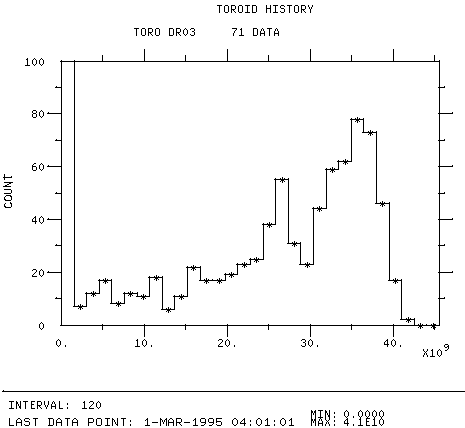
Figure 1b: Histogram of the SDR e+ intensity (1 bunch) over the entire run.

Figure 1a: Histogram of the NDR e- intensity (2 bunches) over the entire run.
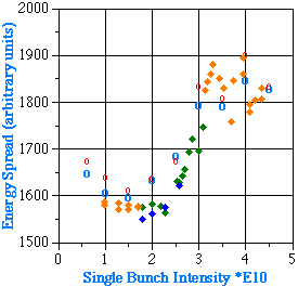
Figure 2: Energy spread of the e- extracted from the NDR, indicating an
instability threshold around 2.3*1010
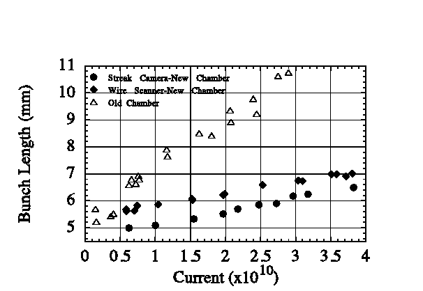
Figure 3: Bunch length measurements in the old and new damping rings
The sawtooth signal remains evident, at much reduced amplitude, in the bunch
length and bunch phase signals. The instability threshold, contrary to
expectation, is in fact now lower at 2.3*1010 compared to 3*1010 with the old
vacuum chamber, as evidenced in the energy spread versus intensity plot shown
in fig. 2. The bunch lengthening with current is far less pronounced, as shown
in fig. 3, and at nominal operating currents there is approximately a factor 2
difference in bunch length compared to the old chamber. In terms of charge
density in the bunch, it is evident that the instability threshold actually
occurs at a higher value than in the old damping ring, but because of the
shorter bunch length this now occurs at a lower beam current.
It is worth noting that the Hamamatsu streak camera was used for the first time
in the damping rings during this run and provided excellent data on the bunch
length behavior. A new wire scanner was also installed in the NRTL at a high
dispersion point to enable energy spread measurements to made after the bunch
compressor. These measurements provided a second method to measure bunch length
in the ring. A similar wire scanner will be installed in the SRTL during this
downtime.
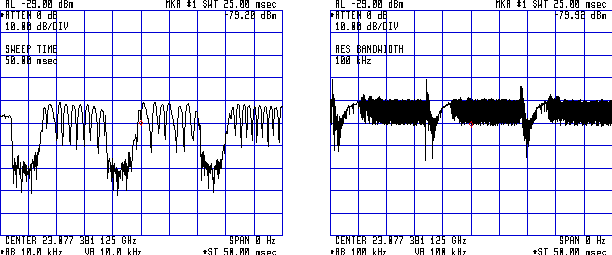
Figure 4: Time dependence over 3 injection cycles of the amplitude of the
instability sideband showing a periodic sawtooth behavior at a) RF voltage of
850 kV and
b) at 800 kV where the sawtooth frequency becomes much higher.
The dynamics of the instability were also studied through observations of the
bunch spectra. With the old vacuum chamber the instability was observed to
generate a longitudinal sextupole mode, close to 3s in frequency. This mode is
no longer apparent in the new chamber, but a new longitudinal quadrupole mode
close to 2s is now evident. The intensity dependence of the frequency of this
mode tells something of the impedance of the vacuum chamber. The linear change
in frequency with current is a result of the reactive part of the impedance,
which in the old ring was inductive and we measured a df/dI of 9 kHz/104.
In the new ring we now measure a df/dI of -6 kHz/104, indicating that
capacitive terms may now dominate the reactive part of the impedance.
The time dependent behavior of the amplitude of the sidebands shows the
risetime and the periodic behavior of the instability. In fig. 4a the
instability sideband grows in the first 4 ms after injection and then
periodically decays and grows following a sawtooth pattern. In fig. 4b the RF
cavity voltage is lowered from 850 kV in the previous figure, to 800 kV. The
amplitude of the instability is less relative to injection and the sawteeth are
smaller and higher in frequency.
A further consequence of the increased beam current is the higher beam loading
in the RF system. The steady state power levels of the damping ring klystrons
are adequate to maintain the desired cavity voltage, but the transients
associated with beam injection are quite severe, particularly in the NDR where
both bunches are injected on the same turn. If left unchecked the beam induced
voltage in the cavity causes large amplitude oscillations resulting in energy
oscillations of the bunch. Since the ring has a limited energy aperture the
beam can be clipped during these oscillations resulting in an increase in the
intensity jitter. In the worst case the oscillations are so large that the
bunch is no longer captured in the RF bucket and "drop outs" in beam intensity
occur.
Transient beam loading is minimized through the use of direct RF feedback as
well as optimizing both the klystron loading angle and the injected beam phase.
Direct RF feedback was originally implemented in the rings to allow the voltage
to be ramped down during the store cycle for controlling the bunch length.
Ramping is not used at present, but the high bandwidth of the feedback loop (~3
MHz) allows it to compensate the beam induced voltage at injection.
The beam loading transient is further reduced by tuning the cavity such that
the klystron loading angle is positive (approximately 10o) during the time the
beam is present. As a result, when the beam is absent and the loading angle
moves to a value equal to the cavity impedance angle (approximately -10o,
feedback on), the real part of the klystron current does not change and there
is less ringing in the cavity voltage.
Finally, the injection phase of the bunch is adjusted to minimize the energy
oscillations the bunch makes in response to the oscillations in cavity voltage.
This is a feed forward principle in that the injection phase is given a preset
offset to compensate for the transient oscillations following injection.
The fine tuning to minimize the effects of transient beam loading were at times
frustrated by problems in the low level RF controls. The cavity tuner loops
were found to be excessively noisy and operating with such a large dead band
that the tuners could only move in large jumps. The klystron department
remedied this during the run. A further problem was found with the gap voltage
controller module not regulating correctly. The gains and offset controls
within the error amplifier were inadequate for the task and although repaired
during the run, will be redesigned during the down time.
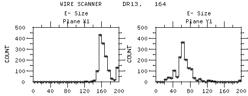
The extracted emittances can be seen in the beam size measurements on the RTL
wires and in the Li02 emittance data, although the latter also includes
emittance dilution effects from the RTLs. The data from these history buffers
is histogrammed in figs 5 and 6. The e- horizontal emittance mean value of
around 3*10-5 in Li02 is better than the e+ value of 4.2*10-5, but this is due
in part to the change in damping partition in the NDR through stretching the
ring circumference. The vertical emittance, on the other hand, is better for
the e+ at around 0.2*10-5 versus 0.4*10-5 for the e- in S2, due largely to the
longer store time in the SDR.
The NDR exhibited a sensitivity to the injected electron emittance from S1,
which led us to impose a tolerance of 20*10-5 mm mrad for the emittances
measured at the Li01 wires. The shorter store time in the NDR relative to the
SDR should not, in theory, account for the observed feedthrough of S1 e-
emittances. However, there is a clear reduction in the emittance, especially in
the vertical plane, when the store time is increased in a low repetition rate
mode. The low e- vertical emittances apparent in the histograms in figs 5 and 6
coincide with "long store" operation. In an effort to understand this effect,
studies were made to measure the emittance contribution from a beta mismatch at
injection. Synchrotron light beam size measurements with the gated camera show
that beta beats in the ring could be minimized by scanning quadrupoles in the
NLTR, but this has not led to any significant emittance reduction in the
extracted beam.

Figure 5: Histograms of the beam size at the RTL wire scanners for the
electrons (top), positrons (bottom) in X (left) and Y (right).
Accurate measurements of the emittance and damping times of the stored beam
have been difficult because of the degraded optics of the synchrotron light
monitor (to be improved during this downtime). A notable difference does exist
between the NDR and SDR (in addition to the stretching of the NDR mentioned
above), and we have performed several ion related experiments to see if this
can account for the differences, particularly the larger e- vertical emittance.
Although ions should be unstable in the damped e- beam we do observe that the
e- have approximately an order of magnitude shorter lifetime than the e+.
Measurements of the betatron tune shift were made during the store time to try
and observe the dynamics of the ion trapping. Several new techniques were
developed for applying small excitations to induce betatron oscillations in the
beam. At the end of the run when the pumps could be turned off, observations
were also made of the tune behavior versus pressure. More work is to be done
before we come to any conclusions about the ions.
The emittance of the extracted beam is very sensitive to the orbit in the
extraction septum regions in both rings. Historically, the stored orbit has
been steered 1 to 2 mm horizontally toward the septum for the extracted beam to
lie in the "good field" region of the septum. The emittance is also very
sensitive to the vertical position of the beam at the septum and our procedure
is to steer the beam in both planes to minimize the skew at the RTL and Li02
wires. Unfortunately, the optimum orbit for extraction is not compatible with
good ring transmission since part of the injected beam is scraped off while
passing too close to the extraction septum . Efforts in the past to improve the
alignment of the septum have failed because of the poor fabrication tolerances
in the vacuum chamber. We have no plans to measure and fix the internal
alignment of any of the septa because of the risks involved in removing the
septa from the rings
The extracted beam orbit is also critical for the strong matching quadrupoles
at the beginning of the RTLs. The rapid phase advance and poor BPM resolution
have made this a difficult region to diagnose. We have especially had
difficulty understanding the extreme sensitivity of the emittance to slight
temperature changes in this region (when the beam and/or magnets are off for
any length of time).

Figure 6: Histograms of the Li02 emittance for the electrons (top), positrons
(bottom) in X (left) and Y (right).
The emittance can increase in the RTLs as a result of a beta mismatch,
chromaticity, dispersion, higher order effects and wakefields in the
compressor. Tuning tools exist for each of these, but difficulties arise when a
tuning procedure compensates for errors from a different source. Compressor-off
emittance measurements (to distinguish the contribution from chromaticity and
dispersion) have been easier to do on a routine basis during this run with the
new 2-9 beam dump. The e+ have been more difficult to do, but a procedure was
developed where the e+ only could be dumped at 60 Hz. Never-the-less, the e+
were diagnosed less often, and we had the unusual behavior that the e+ vertical
emittance actually got larger when the compressor was off. A possible
explanation is the contribution from wakefields in the compressor so its
alignment will be checked again during the downtime. Close to the beginning of
the run we did look for misalignments in the SRTL compressor, but found instead
that the matching quadrupoles were not bolted together. When this was fixed the
quadrupoles could be set closer to their model lattice values and the vertical
emittance in Li02 improved significantly.
The alignment of the RTLs will also be checked to understand the observed
asymmetry in their energy aperture.
The bunch distribution at injection into the linac effects the energy
distribution and tails at the end of the linac. The bunch length in the damping
rings is a function of the gap voltage and the collective bunch lengthening
processes. This bunch length is transformed into energy spread by the RTL
compressor so that the bunch length at injection into the linac is determined
by the compressor voltage and by the energy spread of the bunch in the ring.
Within the ring streak camera measurements of the synchrotron light were used
to measure bunch length as a function of gap voltage and intensity (fig. 3).
The dynamics of the bunch length instability in the ring are visible on a turn
by turn basis by measuring the charge density variations (1/bunch length) from
a BPM.
Bunch length of the extracted beam is inferred from beam size measurements in
the high dispersion regions of the RTLs. With the compressor off this directly
gives the energy spread of the beam in the damping ring. With the compressor on
the bunch length in the ring is calculated by deconvoluting the slope of the
compressor RF from the measured beam size.
The high dispersion RTL wire scanner installed during the run proved far
superior to the earlier diagnostic of video digitization of a profile monitor
screen. The wire scanner does not reveal pulse-to-pulse variations in bunch
length so a new bunch length diagnostic will be installed during the down time.
A high dispersion BPM will be rewired to measure the beam size aspect ratio,
allowing any fluctuations in horizontal beam size (and hence bunch length) to
be monitored.
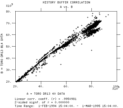
Figure 7: History buffer correlation of current at the beginning and end of the
NRTL, showing losses due to over compression.
At high intensities over compression of the bunch in the RTLs was found to give
a superior energy distribution at the end of the linac. However, over
compression also increases the energy spread in the RTL so that the beam is
scraped in the limited aperture of the high dispersion regions. The relative
beam loss increases with current because of the bunch lengthening within the
damping rings. A history buffer correlation plot of the beam current toroids at
the beginning and end of the NRTL in fig. 7 shows this increase in beam loss
with current. The correlation shows two distinct loss patterns corresponding to
the under compression and over compression modes of operation during this run.
The increasing beam loss with ring intensity must be taken into consideration
when planning future operation at higher currents.
Pulse to-pulse stability (jitter) due to bunch length instabilities in the ring
and due to transient beam loading effects have been covered in previous
sections. The intensity jitter for the e+ is about two times that of the
electrons, as seen in the intensity normalized jitter history plot in fig. 8.
The intensity jitter of the electron bunch which produces positrons is
converted into energy fluctuations due to heavy beam loading in the linac and
in the positron capture and acceleration sections. With a finite energy
aperture, these fluctuations are converted back into intensity jitter. A
succession of such exchanges creates the amplification mechanism.
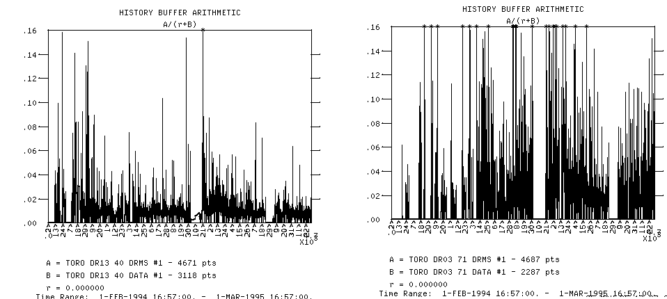
Figure 8: Intensity normalized jitter history at the exit of the NDR (left) and
SDR (right).
The position jitter in the RTLs is worse in the horizontal plane than in the
vertical, as seen in fig. 9. This is due in part to energy fluctuations
downstream of the compressor as a result of phase jitter in the rings and also
because the extraction kickers are in the horizontal plane.
The extraction kicker in the electron damping ring operates with a flat top to
extract both bunches. Small timing errors can place a bunch on the rising or
trailing edge of the kicker pulse, which produces jitter in the extracted kick
angle. This typically contributes about 20% of the observed beam jitter. Timing
scans are periodically done to minimize this effect and a new feedback has been
commissioned to maintain optimal timing.
The NREX and SREX feedbacks try to maintain the energy and orbit of the beam
in the RTLs against fluctuations in the launch parameters and ring extraction
beam phase. The feedback uses the generic SLC fast feedback software which
samples the beam at rates up to 60 Hz. The energy in the RTL is changed by
adjusting the relative phase between the ring RF and the compressor. At the
same time it is desirable to keep the injection phase into the linac constant
to avoid fluctuations in energy spread at the end ofd the linac. The NREX
energy loop actuators were changed in October to act on the ring extraction
phase instead of the compressor phase. In addition to reducing the RTL jitter,
fig. 9, the operator adjustments to the phase ramp (injection phase into the
linac) were also reduced. A similar change was made to the SREX loop sometime
later.
The ring extraction feedback also couples the energy and position jitter
because of the errors in discriminating between position and energy offsets.
Numerous studies were made during the run to make the gain matrices for the
loop more robust and BPMS were added to the loop to improve energy-position
discrimination.
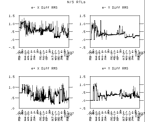
Figure 9a: History buffer data of the rms orbit deviation from the gold orbits
in the NRTL (top) and SRTL (bottom)
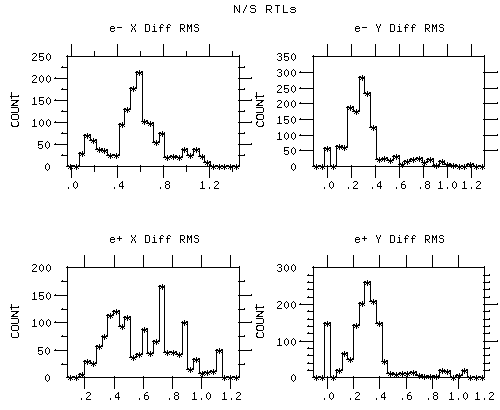
Figure 9b: Histogram of the same data as in fig. 9a above.


