SIS38XX.adl with SIS3820
These drivers support the SIS3801 and SIS3820 multi-channel scalers from Struck Innovative Systems. The SIS3801 was formerly sold as the model STR7201 from a predecessor company called Struck. All are VME modules with 8 or 32 scaler input channels. In this document the term SIS38XX includes all of the above modules, except where explicitly noted. Each input can count at 100MHz or 200MHz depending on model. It has an external channel advance input (called Next) which causes the the current scaler values to be copied to a FIFO, clears the scalers and resumes counting. The scalers are implemented in a dual-bank design, so that the switching time is less than 4 nsec.
The drivers are written to support the use of the SIS38XX as a multichannel scaler. Up to 32 mca records (or waveform records) can be connected to each unit, each record corresponding to one of the signal inputs. There are additional records to control start and stop acquisition of the device, control the dwell time and channel advance source, etc.
The driver also supports using the SIS38XX as a conventional EPICS scaler (like the Joerger scaler) with the scaler record. The SIS3801 does not support counting for a preset time or number of counts, so the preset scaler operation is emulated using the FIFO. The SIS3820 does support counting for a preset counts, and so directly supports the scaler mode of operation without emulation.
The SIS38XX hardware itself is not a multichannel scaler in the conventional sense, since it simply contains a FIFO of scaler counts, rather than an array of memory locations which hold the counts for each dwell cycle. The device support for the SIS38XX simulates a conventional MCS by allocating a memory buffer which contains the counts in each dwell period. The device support copies the counts from the FIFO to this memory buffer. The SIS3801 has a limited amount of FIFO memory (128KB to 512KB), while the SIS3820 comes standard with 64MB, and optionally has 512MB. The SIS3820 also maps a large block (8MB) of the FIFO memory to the VME bus, so it can effectively use DMA operations. The SIS3801 only maps 256 bytes to the VME bus, so DMA cannot be effectively used.
Each FIFO word contains the counts for one input signal for one dwell period. On the SIS3801 the FIFO can thus buffer anywhere from 1024 dwell cycles (32 active inputs, 128KB FIFO) to 128K dwell cycles (1 active input, 512KB FIFO). The minimum dwell time is in the range .5-4 microseconds, depending upon the number of active inputs. VME interrupts are implemented, so that FIFO readout is done automatically when the FIFO is half full. Even with interrupts there is a possibility of FIFO overflow with very short dwell times and small FIFO sizes. Users whose applications require short dwell times and a large number of active inputs should purchase large FIFO chips to prevent this. The FIFO chip can be replaced in the field. The device support determines the FIFO size automatically. On the SIS3820 the FIFO size is large (64MB to 512MB), and can be read out quickly (~ 40 MB/s) using DMA. Still, at 1 microsecond dwell time and 32 active inputs the data rate is 128MB/s, which is 3 times faster than the FIFO readout speed. Thus, users who need very large time sequences at minimum dwell times should chose the 512MB FIFO option.
Jumper J600 on the board must be set to select LCA file 2 (STR7201 Design 1) or LCA file 3 (STR7201 Design 2). With Design 1 selected the scalers are 32 bits wide. With Design 2 selected the scalers are 24 bits wide, and the upper 8 bits of each data word contain information on the channel number, bank, and 2 user bits. The channel number and bank information are redundant since the device support sorts the FIFO output by channel number when copying the data to the buffer and then to the MCA record. However, some applications may want to use the 2 user bits which are latched with each Next cycle, and Design 2 may be selected for those applications.
The device support requires that the board be configured for VME A32 addressing, so jumper EN_A32 must be in place. Address selection is done with jumper J_A11, and switches SW_A32U, SW_A32L, SW_A24 and SW_A16. Note that the factory-default address of 0x33508000 cannot be used with the APS version of the vxWorks board support package since this part of the VME A32 address space is not accessible. Each board takes up 2K bytes of A32 address space.
The A32 address space must be used. The VME A32 base address must be set to a value that is supported by the board support package being used. The SIS3801 occupies 2KB of address space, while the SIS3820 occupies 16MB of address space.
The driver consists of a base class, drvSIS38XX.cpp, and two derived classes, drvSIS3801.cpp and drvSIS3820.cpp. The base class inherits from asynPortDriver, which is part of asyn. The driver uses the standard device-independent asyn device support for the MCA record. The INP link is of the form INP=@asyn(PORT, ADDR), where PORT is the name of the asyn port that has been created for a specific SIS38XX card, and ADDR is the input signal number (0-31).
Alternatively, one can use standard EPICS waveform records for the array data, rather than the mca record. This uses the standard device support for the waveform record that comes with asyn. The example startup scripts (st_SIS3801.cmd and st_SIS3820.cmd) in iocBoot/iocVxWorks contain examples for loading either mca or waveform records.
There is an EPICS SNL program, SIS38XX_SNL.st, that must be run for each SIS38XX card. This is a very simple program that forces each MCA or waveform record to process when acquisition completes before setting the Acquiring busy record back to 0. It also forces each MCA or waveform record to process when the ReadAll record processes. This logic is much easier to accomplish in an SNL program than in a database, particularly because the number of MCA or waveform records in the database is not fixed, but can be changed in the startup script.
The SIS3801 and SIS3820 support was rewritten for R7-0 of the mca module. In previous releases the driver was "synchronous", meaning that the MCA records blocked while the arrays were read from the FIFO on the VME modules. FIFO reads were done with VME program I/O, which can only do about 1000 32-bit words per ms. This was acceptable if the arrays were small (e.g. 2048 channels) because it only took a few ms to read each array. However, some users were beginning to use very large arrays (e.g. 2,000,000 channels). In this case it took several seconds to read each array. Because the MCA records were synchronous, this blocked execution of other EPICS records and tasks while reading the hardware. This was unacceptable, leading to channel access disconnects and other bad effects.
One way to fix this would be to make the drivers asynchronous, meaning that device support will do the I/O in a separate thread, and the records will not block. This is how other slow drivers for the MCA records work, for example the Canberra AIM and the XIA DXP modules. However, this approach cannot be used with the SIS drivers because they must support the EPICS "scaler" record, and the scaler record does not work properly with asynchronous device suppport.
Instead, the drivers were rewritten so that the FIFO is read out into a driver buffer in a low-priority background thread. When the MCA or waveform records process they now just read the data from this driver buffer using a memcpy() call, which is very fast. Furthermore on the 3820 the driver now reads the FIFO using DMA over the VME bus. This yields a factor of 10 improvement in speed, over 40MB/s, compared to 4MB/s with program I/O.
The new drivers have excellent performance with very large arrays, and arrays with more than 10 million elements can now be used if the VME CPU has sufficient memory. For example, a test was done with the following configuration:
The theoretical time for this acquisition to complete is 10 seconds. The following is the output from the EPICS "camonitor" program on a Linux client looking at the Acquiring PV, and the first 2 channels of each waveform record:
    >camonitor -tc -#2 SIS:3820:mca1 SIS:3820:mca2 SIS:3820:Acquiring
    SIS:3820:Acquiring             (2011-05-01 11:19:35.050808) Acquiring
    SIS:3820:mca1                  (2011-05-01 11:19:46.017134) 2 50 50
    SIS:3820:mca2                  (2011-05-01 11:19:46.017223) 2 0 0
    SIS:3820:Acquiring             (2011-05-01 11:19:46.017264) Done
So the time between when acquisition started and when the client received the data and the Acquiring=Done status was 10.97 seconds. There is thus less than 1 second of overhead in collecting 2 waveforms of 10,000,000 elements each, which is 80MB of data.
Note that the DMA function calls used in this driver are to the functions provided in Andrew Johnson's library for vxWorks. It would be very desireable if these functions were included in the EPICS devLib library in EPICS base, so they would work on any EPICS system that can perform DMA. Until this is done users with other DMA libraries will have to write wrapper functions to emulate the API in Andrew Johnson's library.
One instance of the database SIS38XX.template is loaded for each SIS38XX card. This database contains the following records:
| Record | Record type | Description |
|---|---|---|
| $(P)SNL_Connected | bi | Indicates whether the SNL program has connected to all PVs. |
| $(P)EraseAll | bo | Erases all mca or waveform records, setting elapsed times and counts in all channels to 0. |
| $(P)EraseStart | bo | Erases all mca or waveform record and starts acquisition. |
| $(P)StartAll | bo | Starts or resumes acquisition without erasing first. |
| $(P)Acquiring | busy | Acquiring (=1)when acquisition is in progress and Done (=0) when acquisition is complete. |
| $(P)StopAll | bo | Stops acquisition. |
| $(P)PresetReal | ao | Preset real time. If non-zero then acquisition will stop when this time is reached. |
| $(P)ElapsedReal | ai | Elapsed time since acquisition started. |
| $(P)ReadAll | bo | Forces a read of all mca or waveform records from the hardware. This record can be set to periodically process to update the records during acquisition. Note that even if this record has SCAN=Passive the mca or waveform records will always process once when acquisition completes. |
| $(P)NUseAll | longout | The number of channels to use for the mca or waveform records. Acquisition will automatically stop when the number of channel advances reaches this value. |
| $(P)CurrentChannel | longin | The current channel number, i.e. the number of channel advances that have occurred minus 1. |
| $(P)Dwell | ao | The dwell time per channel when using internal channel advance mode. |
| $(P)ChannelAdvance | bo | The channel advance mode. Choices are "Internal" (count for a preset time per channel) or "External" (advance on external hardware channel advance signal). |
| $(P)InitialChannelAdvance | bo | Flag controlling whether an initial software channel advance is done when acquisition starts. If No (=0) then counting does not start in channel 0 until receipt of the first external channel advance pulse in External channel advance mode. If Yes(=1) then counting in channel 0 starts immediately when acquisition starts, without waiting for the first external channel advance pulse. |
| $(P)SoftwareChannelAdvance | bo | Processing this record causes a channel advance to occur immediately, without waiting for the current dwell time to be reached or the next external channel advance pulse to arrive. |
| $(P)Channel1Source | bo | Controls the source of pulses into the first counter. The choices are "Int. clock" which selects the internal clock, and "External" which selects the external pulse input to counter 1. The internal clock is 25MHz on the SIS3801 and 50MHz on the SIS3820. |
| $(P)Prescale | longout | The prescale factor for external channel advance pulses. If the prescale factor is N then N external channel advance pulses must be received before a channel advance will occur. This can be used, for example, to generate a channel advance every 50 stepper motor pulses. |
| $(P)EnableClientWait | bo | Flag to force acquisition to wait until a client clears the ClientWait busy record before proceeding to the next acquisition. This can be useful with the scan record. |
| $(P)ClientWait | busy | Flag that will be set to 1 when acquisition completes, and which a client must set back to 0 to allow acquisition to proceed. This only has an effect if EnableClientWait is 1. |
| $(P)AcquireMode | mbbi | The current acquisition mode (MCS=0 or Scaler=1). This record is used to turn off the scaler record Autocount in MCS mode. |
| $(P)MUXOutput | ao | Value of 0-32 used to select which input signal is routed to output signal 7 on the SIS3820 in output mode 3. |
| $(P)UserLED | bo | Toggles the user LED and also output signal 8 on the SIS3820. |
| $(P)InputMode | mbbo | The input mode. The section below lists the supported input modes for the SIS3801 and SIS3820. |
| $(P)OutputMode | mbbo | The output mode. The section below lists the supported output modes for the SIS3801 and SIS3820. |
| $(P)OutputPolarity | bo | The polarity of the output control signals on the SIS3820. Choices are Normal and Inverted. |
| $(P)Model | mbbi | The scaler model. Values are "SIS3801" and SIS3820". |
| $(P)Firmware | longin | The firmware version. |
| $(P)MaxChannels | longin | The maximum number of channels. |
The SIS3801 supports the following input modes:
The SIS3820 supports the following input modes:
The SIS3801 only supports a single output mode:
The SIS3820 supports the following output modes:
Acqusition will be stopped for all records connected to a driver whenever one or more of the following conditions is satisfied:
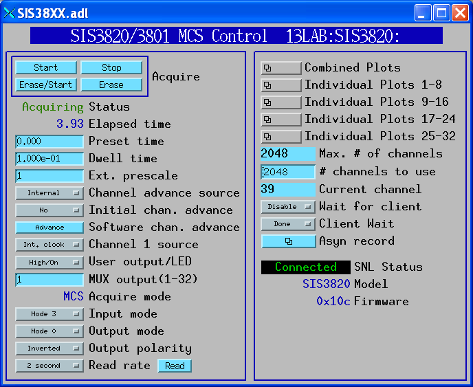
The following shows the MEDM screen for the MCS operation mode of the SIS3820
In addition to support for the MCA record, the driver supports the EPICS scaler record. Switching between scaler mode and MCA mode is handled automatically. It is important, however, that when acquiring in one mode that acquisition be allowed to complete before starting acquisition in the other mode. It is also important when acquiring in MCA mode to disable AutoCount in scaler mode, or else the MCA acquisition may be interrupted. This should be handled automatically by the logic in the database.
The SIS3820 supports true preset-scaler operation, generating a VME interrupt when counting is complete. The SIS3801 does not support this, it simply counts into the FIFO. In scaler mode the driver sets the SIS3801 for an internal channel advance time of 0.01 seconds. It then reads the FIFO 100 times per second and stops as soon as it detects that the preset counts have been reached. This means that it can count for up to 0.01 second longer than the preset value. However, all inputs count for exactly the same time, and the actual time is accurate, so data normalization should be straightforward.
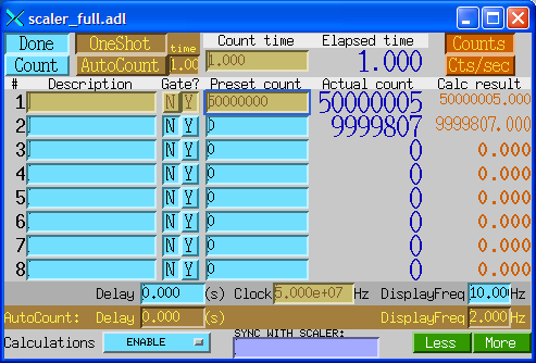
The following shows the MEDM screen for the scaler record with 8 active inputs
The mca/iocBoot/iocVxWorks contains example vxWorks startup scripts for the SIS3801 and SIS3820. st_SIS3820.cmd simply invokes st_SIS3820.iocsh, which contains iocsh commands rather than vxWorks shell commands to allow for the use of environment variables which simplifies the code and makes it easier to understand and modify.
There are 2 functions which are intended to be called from the startup script before iocInit, drvSIS3801Config and drvSIS3820Config
drvSIS3801Config(portName,            # The name of the asyn port to be created
                 baseAddress,         # The base VME A32 address
                 interruptVector,     # The VME interrupt vector
                 interruptLevel,      # The VME interrupt level
                 maxChannels,         # The maximum number of channels (time bins) to use
                 maxSignals)          # The number of inputs to use (1-32)


drvSIS3820Config(portName,            # The name of the asyn port to be created
                 baseAddress,         # The base VME A32 address
                 interruptVector,     # The VME interrupt vector
                 interruptLevel,      # The VME interrupt level
                 maxChannels,         # The maximum number of channels (time bins) to use
                 maxSignals,          # The number of inputs to use (1-32)
                 useDMA,              # Enable DMA (1) or disable DMA (0)
                 fifoBufferWords)     # The number of 32-bit words to read from FIFO into buffer
                                      # Maximum = 2MW = 0x200000
maxSignals is the number of input signals which will be used, in the range 1 to 32. maxSignals controls how many scaler values will be copied to the FIFO each time a Next signal is received. Set this value to the actual number of signals actually being used to conserve FIFO memory on the card and vxWorks buffer memory in the driver. The number of MCA records which can be attached to this card is also controlled by maxSignals.
maxChannels is the maximum number of channels (time points) that will be used in any MCA or waveform record connected to this card. The number of bytes of IOC buffer memory allocated by the driver for this card is maxChans * maxSignals * 4, so set this value to the actual maximum number of channels to be used in any record to conserve memory.