EPICS Record Reference Manual
Advanced Photon Source
Argonne National Laboratory
A single scan record supports a one dimensional scan. It is also possible to link scan records together to define multi-dimensional scans in a complex configuration.
Each scan record can control up to four positioners and acquire data from up to four process variables (typically detector data or measured positions of devices) during a scan. Two additional output variables can be defined to trigger other process variables (usually detectors) between the positioning phase and the data acquisition phase. These outputs will be referred to as detector triggers.
Although the typical use of a scan record is to move positioners and record detector data at each position, it can also be used for other applications. Any controllable device can be scanned through incremental values while recording data from any other process variables. For example, one of the positioner process variables could be used to vary the gain of a detector or the speed of a motor during a scan. Another example would be to use the scan record to vary several power supplies and record the beam position at each value of the supplies. In this context, the scan record becomes a general purpose "Vary w, x, y, z and record a, b, c, d" record. Therefore, throughout this document the word positioner and controller will be used synonymously. When referring to the data being recorded at each point, the word detector will be used.
All of the process variable names used to identify positioners, detectors, and detector triggers are specified using reassignable links. This allows a scan to be configured on the fly.
Scan parameters, including the names of controllers and detectors, can be saved and restored using the BURT.
NOTE: In this version, the PVs used in the reassignable fields must reside in the same IOC.
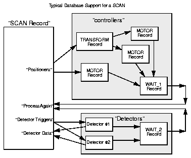
In Figure 1, when the scan is initiated, the scan record commands several positioners (TRANSFORM record and MOTOR record) to move to their starting positions. The WAIT_1 record detects when all movement is complete and forces the SCAN record to process again. The SCAN record realizes that the positioning is complete and thus triggers the Detectors. The WAIT_2 record detects when data is valid and forces the SCAN record to process yet again. The SCAN record will then read the Detector Data and command the positioners to their next step. This will continue until the SCAN record has completed the appropriate number of steps. At the end of the scan, the SCAN record contains data arrays for each of the detectors, as well as arrays that contain the positions to which each controller was commanded at each point. A simple x-y plot using this data will provide the detector data vs. position results.
Figure 10 Typical Database Support for a SCAN
To initiate a scan, the SCAN_Y record is commanded to begin. It commands its positioners to the specified starting point. The WAIT_1 record detects when all motors are stopped and forces the SCAN_Y record to process again. The SCAN_Y record will now write to its Detector Trigger, which in this case begins a scan of the SCAN_X record. The SCAN_X record will now go through its entire programmed scan, acquiring data from the detectors at each point.
When the SCAN_X record is complete, the WAIT_4 record will force the processing of SCAN_Y, which will increment the position of the y-controller and initiate the x scan once again.
This approach to configuring a two dimensional scan is very flexible.
Note that to test the x scan, one could write to the begin scan
field of SCAN_X which would perform an entire x scan. Although the
SCAN_Y record would get processed after the x scan was complete (via the
WAIT_4 record), nothing would happen because it was not in the middle
of a scan. In addition, any of the motors can be moved individually when
a scan is not in process without any unexpected behavior (detectors
would not be triggered unless the operator did it deliberately). One
could even build a three dimensional scan by adding an additional scan
record that initiates the y-scan after positioning a z-controller.
Figure 11 A Two Dimensional Scan 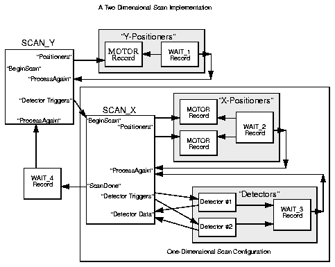
There are three modes for determining the desired value for the
positioner. The desired mode is specified in the P1SM-P4SM fields: Linear,
Table, and On-The-Fly. If a positioner is
specified as Linear, its desired value is determined by
using parameters such as start position, step increment, number of
points, and end position (which are explained below). If a positioner is
specified as Table, its next position is found in an array
that has been loaded into the record prior to initiating a scan. If the
positioner is specified as On-The-Fly, it is commanded to
the end position after the first data point is collected and not changed
again for the duration of the scan.
| Field | Summary | Type | DCT | Initial | Access | Modify | Rec Proc Monitor | PP |
|---|---|---|---|---|---|---|---|---|
| P1SM | Positioner 1 Step Mode | RECCHOICE | Yes | 0 | Yes | Yes | No | No |
| P2SM | Positioner 2 Step Mod | RECCHOICE | Yes | 0 | Yes | Yes | No | No |
| P3SM | Positioner 3 Step Mode | RECCHOICE | Yes | 0 | Yes | Yes | No | No |
| P4SM | Positioner 4 Step Mode | RECCHOICE | Yes | 0 | Yes | Yes | No | No |
Linear, a
scan can be fully defined by three parameters, e.g., the start position
(P1SP), the step increment (P1SI), and the number of data points
(NPTS). A scan involving N controllers is defined by merely 2N+1
parameters, since NPTS applies to all positioners. For the convenience
of interactive users, and to support channel access clients that define
scans differently, the first positioner can be specified by as many as
six parameters: starting position (P1SP), ending position (P1EP), center
position (P1CP), position width (P1WD), step increments (P1SP), and
NPTS. For the other three positioners, the same parameters are available
minus the NPTS field, since that applies to all. The parameters that
pertain to the same positioner are a set. The record imposes an upper
limit (MPTS) on NPTS. Both MPTS and NPTS are configured by the user. The
positioner width, configurable in the P1WD-P4WD fields, may be
negative.
| Field | Summary | Type | DCT | Initial | Access | Modify | Rec Proc Monitor | PP |
|---|---|---|---|---|---|---|---|---|
| NPTS | Number of Points | SHORT | Yes | 100 | Yes | Yes | Yes | No |
| MPTS | Maximum Number of Points | SHORT | Yes | 100 | Yes | No | No | No |
| P1SP | Positioner 1 Starting Point | FLOAT | Yes | 0 | Yes | Yes | Yes | No |
| P2SP | P. 2 Starting Point | FLOAT | Yes | 0 | Yes | Yes | Yes | No |
| P3SP | P. 3 Starting Point | FLOAT | Yes | 0 | Yes | Yes | Yes | No |
| P4SP | P. 4 Starting Point | FLOAT | Yes | 0 | Yes | Yes | Yes | No |
| P1EP | P. 1 Ending Point | FLOAT | Yes | 0 | Yes | Yes | Yes | No |
| P2EP | P. 2 Ending Point | FLOAT | Yes | 0 | Yes | Yes | Yes | No |
| P3EP | P. 3 Ending Point | FLOAT | Yes | 0 | Yes | Yes | Yes | No |
| P4EP | P. 4 Ending Point | FLOAT | Yes | 0 | Yes | Yes | Yes | No |
| P1CP | P. 1 Center Point | FLOAT | Yes | 0 | Yes | Yes | Yes | No |
| P2CP | P. 2 Center Point | FLOAT | Yes | 0 | Yes | Yes | Yes | No |
| P3CP | P. 3 Center Point | FLOAT | Yes | 0 | Yes | Yes | Yes | No |
| P4CP | P. 4 Center Point | FLOAT | Yes | 0 | Yes | Yes | Yes | No |
| P1WD | Positioner 1 Width | FLOAT | Yes | 0 | Yes | Yes | Yes | No |
| P2WD | Positioner 2 Width | FLOAT | Yes | 0 | Yes | Yes | Yes | No |
| P3WD | Positioner 3 Width | FLOAT | Yes | 0 | Yes | Yes | Yes | No |
| P4WD | Positioner 4 Width | FLOAT | Yes | 0 | Yes | Yes | Yes | No |
| P1SI | Positioner 1 Step Increment | FLOAT | Yes | 0 | Yes | Yes | Yes | No |
| P2SI | P. 2 Step Increment | FLOAT | Yes | 0 | Yes | Yes | Yes | No |
| P3SI | P. 3 Step Increment | FLOAT | Yes | 0 | Yes | Yes | Yes | No |
| P4SI | P. 4 Step Increment | FLOAT | Yes | 0 | Yes | Yes | Yes | No |
Some of these fields can be redundant. For instance, the positioner width (P1WD-P4WD) is simply the distance from the starting position to the ending position (PnEP - PnSP). The record calculates redundant parameters for the same set, if the parameters are left undefined. However, the user can still configure the redundant parameters anyway.
There is no unique prescription for removing inconsistencies among redundant parameters, and no hard-coded set of preferences among parameters is likely to please everyone. Therefore, the scan record allows the user to "freeze" parameters with flags so that they will not be changed by the record's internal attempts to ensure consistency among the parameter set. Frozen parameters can be changed by the user and by any other client, but not by the record. It is the user's responsibility to ensure that frozen parameters do not prevent freely specifying unfrozen parameters. For example, if both PnSI and NPTS are frozen, changes to PnWD will be rejected. Similarly, if both PnSP and PnCP are frozen, changes to PnEP and PnWD will have no effect. By default, PnSP, PnSI, and NPTS are frozen. When the record cannot adjust the parameters to be consistent, a flag is raised in the alert field (ALRT) and a message reported in the state message field (SMSG).
The freeze flag override field (FFO) has two choices: Use F-Flags
and Override. Override causes the current
settings of all the freeze flags to be saved and monitors to be called
for those that have changed. Use F-Flags causes the flags saved with the
Override command to be restored if any have changed.
Changing the choice of this field at run-time causes the special record
support routines to perform these actions. So if Override
is chosen at run-time, then all current settings are saved, and can be
restored at a later time by changing the FFO field to Use F-Flags.
| Field | Summary | Type | DCT | Initial | Access | Modify | Rec Proc Monitor | PP |
|---|---|---|---|---|---|---|---|---|
| FPTS | Freeze Flag for NPTS | RECCHOICE | Yes | 1 | Yes | Yes | No | No |
| FFO | Freeze Flag Override | RECCHOICE | Yes | Null | Yes | Yes | No | No |
| PnFS | Positioner n Freeze Flag for PnSP | RECCHOICE | Yes | 1 | Yes | Yes | No | No |
| PnFE | Positioner n Freeze Flag for PnEP | RECCHOICE | Yes | 0 | Yes | Yes | No | No |
| PnFI | Positioner n Freeze Flag for PnSI | RECCHOICE | Yes | 1 | Yes | Yes | No | No |
| PnFC | Positioner n Freeze Flag for PnCP | RECCHOICE | Yes | 0 | Yes | Yes | No | No |
| PnFW | Positioner n Freeze Flag for PnWD | RECCHOICE | Yes | 0 | Yes | Yes | No | No |
Although this approach may seem to present the user with an overwhelming number of choices when it comes to linear scans, it should be noted that by default the user only has to configure NPTS, and the starting position (PnSP) and the step increment (PnSI) fields for each positioner in order to fully define the scan of a positioner. The operator interface (usually DM, medm or another CA client) need only present the user with these fields. However, by changing the freeze flags from the defaults and presenting the user with different fields to fill in, the scan can be defined in a completely flexible way. The result is that a simple scan can be defined easily, but advanced users are not limited in flexibility.
| Field | Summary | Type | DCT | Initial | Access | Modify | Rec Proc Monitor | PP |
|---|---|---|---|---|---|---|---|---|
| P1PA | Positioner 1 Position Array | FLOAT[ ] | No | Null | Yes | Yes | Yes | No |
| P2PA | Positioner 2 Position Array | FLOAT[ ] | No | Null | Yes | Yes | Yes | No |
| P3PA | Positioner 3 Position Array | FLOAT[ ] | No | Null | Yes | Yes | Yes | No |
| P4PA | Positioner 4 Position Array | FLOAT[ ] | No | Null | Yes | Yes | Yes | No |
| Field | Summary | Type | DCT | Initial | Access | Modify | Rec Proc Monitor | PP |
|---|---|---|---|---|---|---|---|---|
| R1PV | Readback 1 Process Variable | STRING [40] | Yes | Null | Yes | Yes | No | No |
| R2PV | Readback 2 Process Variable | STRING [40] | Yes | Null | Yes | Yes | No | No |
| R3PV | Readback 3 Process Variable | STRING [40] | Yes | Null | Yes | Yes | No | No |
| R4PV | Readback 4 Process Variable | STRING [40] | Yes | Null | Yes | Yes | No | No |
| R1DL | Readback 1 Delta | FLOAT | Yes | 0 | Yes | Yes | No | No |
| R2DL | Readback 2 Delta | FLOAT | Yes | 0 | Yes | Yes | No | No |
| R3DL | Readback 3 Delta | FLOAT | Yes | 0 | Yes | Yes | No | No |
| R4DL | Readback 4 Delta | FLOAT | Yes | 0 | Yes | Yes | No | No |
If neither detector trigger field contains a valid PV, the scan record will skip this step and acquire the data immediately. Note that specifying a Detector Trigger requires the scan record to be processed an additional time each point.
| Field | Summary | Type | DCT | Initial | Access | Modify | Rec Proc Monitor | PP |
|---|---|---|---|---|---|---|---|---|
| T1PV | Detector Trigger 1 Process Variable | STRING [40] | Yes | Null | Yes | Yes | No | No |
| T2PV | Detector Trigger 2 Process Variable | STRING [40] | Yes | Null | Yes | Yes | No | No |
| T1CD | Trigger 1 Command | FLOAT | Yes | 0 | Yes | Yes | No | No |
| T2CD | Trigger 2 Command | FLOAT | Yes | 0 | Yes | Yes | No | No |
The scan results will most frequently be read as position arrays (P1PA-P4PA), which are mentioned above, and arrays of detector data (D1PV-D4PV) where each detector data element corresponds to the position element.
For single dimension scans, the scan is complete when the Execute Scan flag (the EXCS) field is set back to zero by the record processing routine (during the scan it is set to 1). The application program can then read the position arrays and the data arrays (or have a monitor set on them so the record will post its monitors when complete).
For two dimension scans similar to Figure 2, the application program should read the arrays from the SCAN_X record after the completion of each x scan and correlate it to the current y controller information. This will allow the application program to display data after each x scan. The scan record will buffer the data for only one x scan, so the application must read the arrays before the next x scan is completed. If the scan is too fast, the application program can contribute to the wait record algorithm such that the y -controllers are not moved until the application program has completely read the previous SCAN_X data.
On slow scans, the application program may want to see that the scan is processed on a point by point basis. Therefore, the scan record will post monitors on fields that it updates each point, but it will not post monitors faster than 20 times per second. If a scan is proceeding at a rate less than 20 points per second, every point will be posted. If a scan is proceeding at 100 steps per second, scalar values will be posted every 5th point (approx.). In either case, the array data will contain every point at the completion of the scan. It is not recommended that the application program use the point to point data except for keeping the operator aware of the progress of the scan.
| Field | Summary | Type | DCT | Initial | Access | Modify | Rec Proc Monitor | PP |
|---|---|---|---|---|---|---|---|---|
| D1PV | Data 1 Process Variable | STRING [40] | Yes | Null | Yes | Yes | No | No |
| D2PV | Data 2 Process Variable | STRING [40] | Yes | Null | Yes | Yes | No | No |
| D3PV | Data 3 Process Variable | STRING [40] | Yes | Null | Yes | Yes | No | No |
| D4PV | Data 4 Process Variable | STRING [40] | Yes | Null | Yes | Yes | No | No |
| EXSC | Execute Scan Flag | SHORT | No | 0 | Yes | Yes | Yes | No |
| D1DA | Detector 1 Data Array | FLOAT[ ] | No | Null | Yes | No | Yes | No |
| D2DA | Detector 2 Data Array | FLOAT[ ] | No | Null | Yes | No | Yes | No |
| D3DA | Detector 3 Data Array | FLOAT[ ] | No | Null | Yes | No | Yes | No |
| D4DA | Detector 4 Data Array | FLOAT[ ] | No | Null | Yes | No | Yes | No |
Other than that, the High Range and Low Range value fields are only used as the display limits for an operator interface. The same is true for the rest of these fields, which are configured to affect the information displayed to the operator. Each positioner and the detector for each positioner have the following fields:
| Field | Summary | Type | DCT | Initial | Access | Modify | Rec Proc Monitor | PP |
|---|---|---|---|---|---|---|---|---|
| P1EU | Positioner 1 Eng. Units | STRING [16] | Yes | 16 | Yes | Yes | No | No |
| P1HR | Pos. 1 High Range | FLOAT | Yes | 0 | Yes | Yes | No | No |
| P1LR | Pos. 1 Low Range | FLOAT | Yes | 0 | Yes | Yes | No | No |
| P1PR | Pos. 1 Precision | SHORT | Yes | 0 | Yes | Yes | No | No |
| P2EU | Pos. 2 Eng Units | STRING [16] | Yes | 16 | Yes | Yes | No | No |
| P2HR | Pos. 2 High Range | FLOAT | Yes | 0 | Yes | Yes | No | No |
| P2LR | Pos. 2 Low Range | FLOAT | Yes | 0 | Yes | Yes | No | No |
| P2PR | Pos. 2 Precision | SHORT | Yes | 0 | Yes | Yes | No | No |
| P3EU | Pos. 3 Eng Units | STRING [16] | Yes | 16 | Yes | Yes | No | No |
| P3HR | Pos. 3 High Range | FLOAT | Yes | 0 | Yes | Yes | No | No |
| P3LR | Pos. 3 Low Range | FLOAT | Yes | 0 | Yes | Yes | No | No |
| P3PR | Pos. 3 Precision | SHORT | Yes | 0 | Yes | Yes | No | No |
| P4EU | Pos. 4 Eng Units | STRING [16] | Yes | 16 | Yes | Yes | No | No |
| P4HR | Pos. 4 High Range | FLOAT | Yes | 0 | Yes | Yes | No | No |
| P4LR | Pos. 4 Low Range | FLOAT | Yes | 0 | Yes | Yes | No | No |
| P4PR | Pos. 4 Precision | SHORT | Yes | 0 | Yes | Yes | No | No |
| D1EU | Detector 1 Eng. Units | STRING [16] | Yes | 16 | Yes | Yes | No | No |
| D1HR | Det. 1 High Range | FLOAT | Yes | 0 | Yes | Yes | No | No |
| D1LR | Det. 1 Low Range | FLOAT | Yes | 0 | Yes | Yes | No | No |
| D1PR | Det. 1 Precision | SHORT | Yes | 0 | Yes | Yes | No | No |
| D2EU | Det. 2 Eng. Units | STRING [16] | Yes | 16 | Yes | Yes | No | No |
| D2HR | Det. 2 High Range | FLOAT | Yes | 0 | Yes | Yes | No | No |
| D2LR | Det. 2 Low Range | FLOAT | Yes | 0 | Yes | Yes | No | No |
| D2PR | Det. 2 Precision | SHORT | Yes | 0 | Yes | Yes | No | No |
| D3EU | Det. 3 Eng. Units | STRING [16] | Yes | 16 | Yes | Yes | No | No |
| D3HR | Det. 3 High Range | FLOAT | Yes | 0 | Yes | Yes | No | No |
| D3LR | Det. 3 Low Range | FLOAT | Yes | 0 | Yes | Yes | No | No |
| D3PR | Det. 3 Precision | SHORT | Yes | 0 | Yes | Yes | No | No |
| D4EU | Det. 4 Eng. Units | STRING [16] | Yes | 16 | Yes | Yes | No | No |
| D4HR | Det. 4 High Range | FLOAT | Yes | 0 | Yes | Yes | No | No |
| D4LR | Det. 4 Low Range | FLOAT | Yes | 0 | Yes | Yes | No | No |
| D4PR | Det. 4 Precision | SHORT | Yes | 0 | Yes | Yes | No | No |
| NAME | Record Name | STRING [29] | Yes | 0 | Yes | No | No | No |
| DESC | Description | STRING [29] | Yes | Null | Yes | Yes | No | No |
The Code Version (VERS) field reflects the version of scan record processing routines.
The VAL field is not used.
The State Message (SMSG) field holds a message sent by the record that alerts the operator to an error condition. It can be cleared by writing a 0 to the Command (CMND) field. The CMND field sends two commands: Clear the State Message field (SMSG), which corresponds to 0; and Execute a "dry run", checking the desired position against the range limits for each positioner, this command corresponding to 1.
The Alert (ALRT) field is a flag which indicates if an error condition currently exists. 1 means YES; 0, NO. The cause of the condition will be displayed in the SMSG field.
The Current Point (CPT) field contains the current point of an active scan. The Desired Value fields for each positioner (P1DV-P4DV) contain the desired value of each positioner for the current point (CPT) in the scan. The Readback Current Value (R1CV-R4CV) fields contain the current readback value for each positioner. The Detector Current Value (D1CV-D4CV) contain each detector's current value for the current point in the scan. The event posting for these fields is throttled to 20 Hz, so for fast scans not every value will be posted.
The PCPT, PXSC, P1LV-P4LV, R1LV-R4LV, and D1LV-D4LV fields all contain the previous or "last" value for their corresponding fields. For instance, the R1LV field contains the last value for the R1CV field. These fields are used to implement monitors for the corresponding field. For instance, if CPT does not equal PCPT when the record is processed, then monitors are triggered for CPT.
The Name Valid fields (xxNV) are flag fields which indicate if the corresponding process variable field contains an existing process variable. For instance, the P1NV field indicates if the P1PV field contains valid process variable; the R4NV field indicates whether R4PV contains a valid, existing process variable, and so on. These fields are used to decide if a process variable has been configured by the user. If not, the fields associated with that variable are ignored.
The Database Address fields (xxDB) are of normally of interest only to the record itself, and are not even accessible at run-time. They contain pointers to the dbAddr structures of the corresponding process variables. For instance, P1DB points to the dbAddr structure of P1PV.
| Field | Summary | Type | DCT | Initial | Access | Modify | Rec Proc Monitor | PP |
|---|---|---|---|---|---|---|---|---|
| VERS | Code Version | FLOAT | No | 1.0 | Yes | No | No | No |
| VAL | Value Field | DOUBLE | No | 0 | Yes | Yes | No | No |
| SMSG | State Message | STRING [40] | No | Null | Yes | Yes | Yes | No |
| CMND | Command Field | ENUM | No | 0 | Yes | Yes | Yes | No |
| ALRT | Alert Field | UCHAR | No | 0 | Yes | No | Yes | No |
| RPVT | Record Private | NOACCESS | No | Null | No | No | No | No |
| PXSC | Previous Execute Scan | UCHAR | No | 0 | Yes | No | No | No |
| CPT | Current Point | SHORT | No | 0 | Yes | No | Yes* | No |
| PCPT | Previous Current Point | SHORT | No | 0 | Yes | No | No | No |
| TOLP | Time of Last Posting | ULONG | No | 0 | Yes | No | No | No |
| P1NV | Pos. 1 Name Valid | LONG | No | 0 | Yes | Yes | Yes | No |
| P2NV | Pos. 2 Name Valid | LONG | No | 0 | Yes | Yes | Yes | No |
| P3NV | Pos. 3 Name Valid | LONG | No | 0 | Yes | Yes | Yes | No |
| P4NV | Pos. 4 Name Valid | LONG | No | 0 | Yes | Yes | Yes | No |
| R1NV | Readback 1 Name Valid | LONG | No | 0 | Yes | Yes | Yes | No |
| R2NV | Rbk. 2 Name Valid | LONG | No | 0 | Yes | Yes | Yes | No |
| R3NV | Rbk. 3 Name Valid | LONG | No | 0 | Yes | Yes | Yes | No |
| R4NV | Rbk. 4 Name Valid | LONG | No | 0 | Yes | Yes | Yes | No |
| T1NV | Trigger 1 Name Valid | LONG | No | 0 | Yes | Yes | Yes | No |
| T2NV | Trigger 2 Name Valid | LONG | No | 0 | Yes | Yes | Yes | No |
| D1NV | Data 1 Name Valid | LONG | No | 0 | Yes | Yes | Yes | No |
| D2NV | Data 2 Name Valid | LONG | No | 0 | Yes | Yes | Yes | No |
| D3NV | Data 3 Name Valid | LONG | No | 0 | Yes | Yes | Yes | No |
| D4NV | Data 4 Name Valid | LONG | No | 0 | Yes | Yes | Yes | No |
| P1DV | Pos. 1 Desired Value | FLOAT | No | 0 | Yes | No | Yes* | No |
| P1LV | Pos. 1 Last Value | FLOAT | No | 0 | Yes | No | No | No |
| R1CV | Readback 1 Current Value | FLOAT | No | 0 | Yes | No | Yes* | No |
| R1LV | Readback 1 Last Value | FLOAT | No | 0 | Yes | No | No | No |
| P2DV | Pos. 2 Desired Value | FLOAT | No | 0 | Yes | No | Yes* | No |
| P2LV | Pos. 2 Last Value | FLOAT | No | 0 | Yes | No | No | No |
| R2CV | Readback 4 Current Value | FLOAT | No | 0 | Yes | No | Yes* | No |
| R2LV | Readback 2 Last Value | FLOAT | No | 0 | Yes | No | No | No |
| P3DV | Pos. 3 Desired Value | FLOAT | No | 0 | Yes | No | Yes* | No |
| P3LV | Pos. 3 Last Value | FLOAT | No | 0 | Yes | No | No | No |
| R3CV | Readback 4 Current Value | FLOAT | No | 0 | Yes | No | Yes* | No |
| R3LV | Readback 3 Last Value | FLOAT | No | 0 | Yes | No | No | No |
| P4DV | Pos. 4 Desired Value | FLOAT | No | 0 | Yes | No | Yes* | No |
| P4LV | Pos. 4 Last Value | FLOAT | No | 0 | Yes | No | No | No |
| R4CV | Readback 4 Current Value | FLOAT | No | 0 | Yes | No | Yes* | No |
| R4LV | Readback 4 Last Value | FLOAT | No | 0 | Yes | No | No | No |
| D1CV | Detector 1 Current Value | FLOAT | No | 0 | Yes | No | Yes* | No |
| D1LV | Detector 1 Last Value | FLOAT | No | 0 | Yes | No | No | No |
| D2CV | Detector 2 Current Value | FLOAT | No | 0 | Yes | No | Yes* | No |
| D2LV | Detector 2 Last Value | FLOAT | No | 0 | Yes | No | No | No |
| D3CV | Detector 3 Current Value | FLOAT | No | 0 | Yes | No | Yes* | No |
| D3LV | Detector 3 Last Value | FLOAT | No | 0 | Yes | No | No | No |
| D4CV | Detector 4 Current Value | FLOAT | No | 0 | Yes | No | Yes* | No |
| D4LV | Detector 4 Last Value | FLOAT | No | 0 | Yes | No | No | No |
| P1DB | Pos. 1 dbAddr | NOACCESS | No | Null | No | No | No | No |
| P2DB | Pos. 2 dbAddr | NOACCESS | No | Null | No | No | No | No |
| P3DB | Pos. 3 dbAddr | NOACCESS | No | Null | No | No | No | No |
| P4DB | Pos. 4 dbAddr | NOACCESS | No | Null | No | No | No | No |
| R1DB | Readback 1 dbAddr | NOACCESS | No | Null | No | No | No | No |
| R2DB | Readback 2 dbAddr | NOACCESS | No | Null | No | No | No | No |
| R3DB | Readback 3 dbAddr | NOACCESS | No | Null | No | No | No | No |
| R4DB | Readback 4 dbAddr | NOACCESS | No | Null | No | No | No | No |
| T1DB | Trigger 1 dbAddr | NOACCESS | No | Null | No | No | No | No |
| T2DB | Trigger 2 dbAddr | NOACCESS | No | Null | No | No | No | No |
| D1DB | Detector 1 dbAddr | NOACCESS | No | Null | No | No | No | No |
| D2DB | Detector 2 dbAddr | NOACCESS | No | Null | No | No | No | No |
| D3DB | Detector 3 dbAddr | NOACCESS | No | Null | No | No | No | No |
| D4DB | Detector 4 dbAddr | NOACCESS | No | Null | No | No | No | No |
Generated with Harlequin WebMaker