LCLS
SLC-Aware IOC
Magnet Functional Specification

Contact:  Kristi Luchini
Last Updated:  June 2, 2005

Table of Contents

1  Introduction
2  Requirments
3  Device Control and Monitor
3.1 Magnet Functions
3.2 Magnet Handler Thread
3.3 Magnet Monitor Thread
3.4 Magnet Asyn Thread
4  Database
4.1 Primaries
4.2 Naming Convention
5  Displays
5.1 SCP Displays
5.2 EPICS EDM Displays
6  Applications
7  Error Message Logging
8  Diagnostics
9  Lose Ends


1 Introduction

2 Requirements

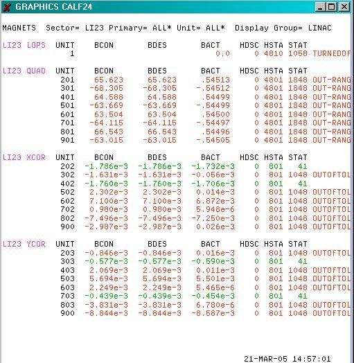
The LCLS magnets controls must be able to operate at a rate from 10Hz up to 120Hz . The new LCLS magnets must be able tobe monitored and controlled from the SLC SCP.  Since LCLS is sharing the use of the Linac with End-Station A, any software and/or hardware changes needed to switch between running the Linac in LCLS mode vs SLC mode for End-Station A, shall not take longer than 15 minutes. Therefore, any SLC database changes necessary to run any existing magnets in LCLS mode must be reset to their SLC state within the time restrictions prescribed.  In addition, the VME hardware used to control and monitor the magnets from EPICS shall exhibit a minimum of the same properties on a magnet  SCP displays as the existing SLC magnets, providing transparency of operation to the operators.  New EPICS displays will be required to control and monitor. In Phase I, all LCLS magnets with the exception of the Undulator can be monitored from an EPICS EDM display as well as an SLC SCP display. However,  it is not required that the users be able to control an old SLC magnet ps from an EPICS display. This capability will be provided, but may not be availalbe on day 1.

3 Device Control and Monitor

The SLC micro magnet job currently handles both magnet and magnet-like devices. A magnet device is a controllable magnet  with power supply, whereas magnet-like device is not a magnet at all. These devices are simply defined in the SLC database by a subset of the magnet secondaries and as such are controlled and monitored by the the magnet software.  Table 4.1-1 below provides a list of  SLC database magnet primaries.  It is important to note that Table 2-1 also provides magnet primaries that are used by modeling programs and modeling applications such as LEM,steering and chormaticity but that the SLC micros do not use to control a magnet device

3.1 Magnet Functions

To maintain functionality the SLC-Aware IOC will proivid a magnet facility to control (hdnlr) and monitor (async) both magnet and magnet-like devices. The standard magnet funtions listed in table 2-2 below will be supported fromVMS via the messages service which will send a request to the EPICS ioc by performing a dbput.  The EPICS magnet software will only deal with magnet devices. All primaries dealing with stepper controls and other magnet-like devices will be handled separately.

Magnet functions are sent from the Alpha to the micro, where the messages are proccessed and the appropriate action is then taken. There are also some functions performed directly on the Alpha via virtual CAMAC, this type of access will not be supported. However, there is one function that turns on/off  Large Power Supplies (LGPS) using virtual CAMAC. This functionality will be supported and extend to include other magnet power supply on/off control. Degaussing is another function that is performed on the Alpha.  Degaussing gets rid of the residual field. This function is necessary for LCLS injector magnets. So extending this existing code will be necessary as well as extending the standalone ACCESS to include a new DCL verb for degaussing.  

Below are tables listing the magnet functions found on the micro and the VAX. Please note that the functions that will not be supported are hightlighted in yellow.

Table 3.1-1
Micro Magnet Functions

Function Codes
Action Reply Msg
Supported
MGNT_CALB Calibrate No
Yes
MGNT_DCAL Calibrate with extra diagnostics No
Yes
MGNT_STDZ Standardize No
Yes
MGNT_PTRB Move to a setpoint Yes
Yes
MGNT_ZERO Zero the DAC Yes
Yes
MGNT_CHCK Update readback in database now No
Yes
MGNT_TRIM Adjust until the setpoint and readback are within tolerance Yes
Yes
MGNT_RSET Reset hardware, restore setpoint, get readback
No
MGNT_TOUC Adjust only if setpoint and readback are close but not close enough Yes
Yes
MGNT_DAOC Move to a setpoint but don't get a readback
Yes
MGNT__ACT Set actual current to desired current. (IACT to IDES)
Yes
Yes

Table 3.1-2
VAX Magnet Functions

Function
Description
Supported
LGON
Turn on large ps
Yes
LGOF
Turn off large ps
Yes
DEGA
Degauss
Yes
PSON
Magnet ps on
New
PSOF
Magnet ps off
New

3.2 Magnet Handler Thread

The magnet request handler is a task run on the SLC Aware IOC that handle magnet messages (see Table 3.3-2). This task is started by DBEXEC after boot. The magnet messages can originate either locally or from a process on the Alpha such as a SCP or from Paranoia.  The following is functional what will occur:
  1. Create a message queue.
  2. Initialize magnet and magnet-like device db lists.  These db lists will be global to magnet tasks only.
  3. Do some consistency checking between some EPICS pv's and SLC db pv's. EPICS PV's are the master at this point.
  4. Log messages if inconsistencies found, and update local db for all but supertype 1.
  5. Set a done init flag when finished. This flag is to be used for internal diagnostics only.
  6. Set the magnet handler active flag to TRUE
  7. Begin metering messags
  8. Enter a while loop waiting for messages in the queue (click here) or stop flag set. If stop flat exit loop.
  9. Set the magnet handler active flag to FALSE.
  10. Perform any cleanup
  11. Exit
Processing a message found in the queue.
    1. Read message from the queue.
    2. If this is a local message IOC_ASYNC and messages are pending in the queue, drop this message on the floor and exit. Otherwise, continue.
    3. If this is not a local message then setup reply if one is required. Note that some reply messages don't return data. See Table 3.31
    4. Set magnet activity in CSTR MAGF to no activity, IDLE  (ie: zero).
    5. Read VAL field for all magnet adc's (do not force a read).
    6. calculate time to do the read in step 5
    7. If function is  not an IOC_ASYNC or a MGNT_CHECK setup for a timeout based on the type of magnet function.
    8. <>
    9. Set the EPICS pv channel <PRIM>:<MICR><UNIT>:CTRL to the function being performed, such as TRIM.
    10. Set the  STA2 busy bit to "1" and do a dbupdate(). This STA2 bit corresponds to the EPICS pv channel  <PRIM>:<MICR>:<UNIT>:BUSY  
    11. Set a monitor on the pv <PRIM>:<MICR>:<UNIT>:BUSY  (make sure to lockout)
    12. When this channel changes state from busy to idle this will indicate that the control function has completed and all associated EPICS pv's have been updated by the mgntMonitor task .
    13. Remove the monitor on the <PRIM>:<MICR>:<UNIT>:BUSY  (make sure to lockout)
    14. Update the CSTR MAGF secondary with the magnet function being processed if the "terse" bit is not set in the magnet function, BDES has changed. Note, this secondary is micro wide and not unit wide. So it is used mainly for functions which hang up the micro for a long period of time, such as a standardize and calibrate, diagnostic calibrate and trim. All magnet functions where the "terse" bit is not set will need to update CSTR MAGF secondary. After updating CSTR a dbsend is issued. Alpha code (ref_magutil: mgntactivity.for) translates the magnet function code in MAGF to an ascii string and displays it on a SCP display.
    15. Release the received message from the message buffer.
A magnet message consists of a header and a triplet consisting of a primary, and a unit range.

header
primary
first unit
last unit

The message header consists of

source
destination
VMS timestamp
function code
datalen

Those magnet messages the return a reply message will send the following, with the exception of the magnet calbrate diagnostic function which returns more that an status to the source.

header
status

  In the Callback:
1. Issue  a dbupdate if required. (TERSE bit not set in magnet function, BDES change, or periodic function)
2. If reply message is required, then add return status and send reply

3.3 Magnet Monitor Threads

There will be three separate threads whose function will be to monitor supertype 1,2 and 3 secondary changes occuring in the EPICS database.

Each SLC database magnet unit will have corresponding EPICS database pv's with the following naming convension.

 <PRIM>:<MICR>:<UNIT>:<SECN>

where the secondary is listed in the tables found below. The list of magnet secondaries that will have corresponding EPICS pv's ae listed in Table 3-3.1 below.

Table 3.31
Secondary
Description
Supertype
Size
CA Monitor
CA Security
BDES
Desired B-Field
2
float
Yes
No
HSTA
Hardware Status
2
unsigned short
Yes
No
IVBU
Current vs B-Field going up
1
variable float
No
Yes
IVBD
Current vs B-Field going down
1
variable float
No
Yes
TOLS
Tolerance on BDES
1
float[4]
No
Yes
IMMS
Final setpoint for STDZ and CALB
1
float[2]
No
Yes
IMMO
Min and max current for operating conditions
1
float[3]
 No
Yes
NSCY
Num of STDZ cycles (up/down=1)
Interval in msec between going down
1
float[2]
No
Yes
SETL
Settle tiime in msec for PS to stabalize
1
short
No
Yes
DVIC
Calibrated DAC=F(I)
3
variable float
No
Yes
DVIG
Calibrated DAC=F(I) goodness from fitting
3
variable float
No
Yes
STAT
Status bitmask
3
unsigned short
Yes
No
STAT2
Status 2 bitmask
3
unsigned long
Yes
No
IDES
Desired current, calculated from BDES
3
float
Yes
No
IPRV
Last recorded current in tolerance
3
float
Yes
No
BACT
B-Field last read
3
float
Yes
No
IACT
Current last read
3
float
Yes
No
RIPL
Ripple readback
3
float
Yes
No
IMAX
Max (or min) recorded current for STDZ magnets
3
float
Yes
No
ITRY
Number of tries required to TRIM
3
unsigned short
Yes
No
TTIM
Last time successfully  Trimmed
3
unsigned long[2]
No
No
CTIM
Last time successfully Calibrated
3
unsigned long[2]
No
No
KTIM
Last time successfully Standardized
3
unsigned long[2]
No
No
ZTIM
Last time Standardize was lost
3
unsigned long[2]
No
No
IMON
Second analog signal (reference)
3
float
Yes
No
BMON
Redundant transducer readback
3
float
Yes
No

The monitor threads will be started from the mgntHdlr thread after initialization has been performed but prior to setting the init done event flag. The reason for this is to have these threads place monitors prior to the mgntAsync thread running and the mgntHdlr begins processing magnet functions from it's message queue.  This is important during boot so that any inconsistencies between the SLC and EPICS database can be rectified and/or a message logged.

1. When entering a thread the active flag should be set.
2. Monitors will be placed on the EPICS pv's corresponding to the secondaries listed in the tables below.
3. If a monitor fires due to a change, then a check is done to determine if the EPICS PV  <PRIM>:<MICR>:<UNIT>:CTRL is "BUSY". If yes, the event is ignore because mgntHdlr is performing an action on this channel and a number of pv's may be expected to be updated as a result of the magnet function being performed.  If the pv was a nTIM then make sure to convert the EPICS time to a VMS timestamp before updating the database on the SLC Aware side. If the unit was not "BUSY", then perform a dblput and  followed by a dbupdate.

In the SLC micro job the data shipped from the micro to the Alpha depends on the secondary and in some cases how much the value has changed.  This intelligence will be placed in EPICS database or and EPICS sequence.. This is an issue to be decided in the design phase.

The use of an unused bit in the STA2 secondary might be used to indicate that a magnet device is "BUSY".  The EPICS pv <PRIM>:<MICR>:<UNIT>:CTRL would be a binary input that gets it's data from decoding the multibit binary used for the STA2.  This is to be decided in the design phase as well.

Note:  For those variable length secondaris the EPICS pv would more than likely be a waveform. However, it is important to not taht channel access monitors are not available for waveform records. As such another mechanism will have to be used to detect changes in these EPICS pv's. For waveform pv's that are supertype 1 and, I don't know if waveforms can be monitored.


Tabel 3.3-2
Monitor Tasks

Name of Thread
Description
mgntMonitorS1
Monitor changes to supertype 1 secondaries reflected in  EPICS pv's
mgntMonitorS2
Monitor changes to supertype 2 secondaries reflected in EPICS pv's
mgntMonitorS3
Monitor changes to supertype 3 secondaries reflected in  EPICS pv's

3.4 Magnet Async Thread

The magnet asynchronous thread

4 Database

4.1 Primaries

The magnet primaries include both magnet and magnet-like devices. Magnet-like devices are stepper motors, dumb dac outputs that don't have readbacks and a few miscellenous odds and ends. The table H3-1 below lists all magnet primaries on SLC.  Some of these primaries are used only on the Alpha, such as BNDS which provides information for modeling programs that run on the Alpha.  The primaries listed in Table 4.1-1 highlighted in purple are magnet-like devices which are controlled by the SLC Micro job. The primaries listed in Table 4.2-1 highlighted in yellow are used only by the modeling application run on the Alpha.

Table 4.4-1
Magnet Primaries

Prim
Description
Supported
Type
LGPS
Large Power Supplies
Yes
magnet
QUAD
Quadrupoles
Yes
magnet
XCOR
X Correctors
Yes
magnet
YCOR
Y Correctors
Yes
magnet
LENS
Polarized source magnets - Lenses
Yes
magnet
SEXT
Sextupole
Yes
magnet
SEPT
Septum Magnets
Yes
magnet
BEND
Bending magnet (used for modeling only)
Yes
magnet
BTRM
Bending magnet with a trim coil
Yes
magnet
QTRM
Quad with a trim coil
Yes
magnet
SMPS
Small power supply
SAM/DAC with digital on/off control and status
Yes
magnet
PHAS
Phase control devices
Yes
magnet-like
AMPL
Amplitude Control devices
Yes
magnet-like
STEP
Stepper Motor Controller
Yes
magnet-like
XMOV
Arc mover magnet X-direction
Yes
magnet-like
YMOV
Arc mover magnet Y-direction
Yes
magnet-like
SPTS
Septum magnet strings
Yes - not used by LCLS
used by model and model apps only
BNDS
Bending magnet strings
Yes
used by model and model apps only
QUAS
Quadrupole strings
Yes
used by model and model apps only
SOLS
Solenoid strings
Yes
used by model and model apps only

4.2 Naming Convension

             4.2.1  Magnet PV Attributes vs SLC Database Fields
             4.2.2  Naming Convention for Control System Devices

4.3 Status Secondaries

The hardware status HSTA and status STAT are status words used to color code the SCP displays indicating a magnet in good condition, warning, sick, or failed state. These bitmaks are used extensively for diagnoising problems with a magnet. As not all bits in these two words are necessary for the new LCLS magnet power supply controllers Table below in this section list the bits that will be supported.

Table 4.3-1
Hardware Status Bitmask
HSTA
Bit Number
Description
Supported
0
Good ( hw in service)
Yes
1
Unused
n/a
2
Dead (hw dead set offlline)
Yes
3
Sick (hw malfunction)
Yes
4
Offline (hw offline/turned off by VAX)
Yes
5
Reverse (hw polarity switch state)
No
6
Feedback control
Yes
7
Mini standardize required
Yes
8
Disable calibrate
Yes
9
Disable perturb
Yes
10
Disable trim
Yes
11
Disable standardize
Yes
12
No retry on trim
Yes
13
Use IVBD polynomial
Yes
14
Device is shunted
Yes
15
Disable automatic trim
Yes

Table 4.3-2
Status Bitmask
STAT
Bit Number
Description
Supported
0
Good
Yes
1
Warning
Yes
2
Dead
Yes
3
Sick
Yes
4
Offline Yes
5
Standardize OK
Yes
6
Calibrate OK
Yes
7
BACT Drifted
Yes
8
Database Error
Yes
9
DAC Error
No
10
ADC Error
Yes
11
Invalid Current
Yes
12
Out of tolerance
Yes
13
Invalid Ripple
Yes
14
Invalid BACT
Yes
15
Not used
n/a

Tabel 4.3-3
Status 2 Bitmask
STA2
Bit Number
Description
Supported
0
Current Moving
Yes
1
Ramp In Progress
Yes
2
Ramp Pending
Yes
3
In Local Mode
NO
4
Infor Message Available
No
5
Bad Auxillary Readback
No
6
Prim/Aux Readback Out of Tolerance
No
7
Interlock Fault
Yes
8
BUSY
May be added
9
unused
unused
10
unused
n/a
11
unused
 n/a
12
unused
n/a
13
unused
n/a
14
unused
n/a
15
unused
n/a

5 Displays

5.1 SCP Displays

The SCP Magnet Displays are color coded. The status represented by the color is listed below in Table 5.1-1.
A combination of the STAT,STAT2 and HSTA secondaries are used to determine which color coding is used for a unit on the Magnet Displays below.

Table 5.1-1
Color
Status Description
Red (looks brown below on displays)
Error
Yellow
Warning
Green
Good


The CSTA secondary is only used for the LGPS primaries only. This secondary is the data from a CAMAC module status register. The hardware that will be used for LCLS ps controllers will have a status register, but it will be in VME. The VME registers in question will have different information available. We can use the CSTA secondary to show both VME and CAMAC status information, or when the Scp Magnet Diagnostic Display  "Decode Diag Info" button is selected for a device controlled by EPICS then a caget rather than a dbget can be used to obtain this information and then decode it on the display.


5.2 EPICS EDM Displays

Need additional EPICS displays for interlocks related to the PSI PSC controller as well as individual control displays for the injector, the linac sectors 21-30, the beam switch yard, linac to undulator, and the dump. It is unclear at this point if displays will be necessary for the undulator section of the machine as there will be no EPICS control or monitoring for the magnet devices in this area. The magnets in the undulator and the LTU will also not be represented in SLC database, which therefore implies that high level SCP applications for modeling, correlation plots and history buffering will not be available.  In phase I the EPICS displays for magnets will maintain a similar layout and the same status color coding used on the magnet SCP panel displays. The reason for this is to provide consistency for users and developers  while switching between both systems as well as for diagnostic purposes when diagnoising a magnet problem.

6 Applications

The required high level software applications on SLC that will be required on the Alpha by LCLS will be shown below. These facilities require that magnet devices be defined in the SLC database.
  1. Correlation Plots
  2. History Plots
  3. History Buffering
  4. Gold and Configuration Files
  5. Error Logging
  6. Access
  7. MultiKnobs
  8. Button Macros
  9. EDM
  10. Matlab
  11. Modeling - DIMAD
  12. Modeling Application
  13. a. LEM
    b. Steering
    c. Chromaticity
    The required high level software applications with EPICS Channel Access Linux that will be required LCLS and run under Linux are listed below.

    1. EDM
    2. Channel Archiver
    3. Channel Watcher
    4. CMLOG
    5. Save/Restore
    6. Matlab
In furture, in phase 2, additional high level applications will be developed to replace those used on the Alpha during phase i.

7  Error Messages Logging

Two level of logged messages will be employed, local messages and global messages. The local messages will be displayed only on the local CMLOG browser or SLC SCP message window. A global message will be seen on all CMLOG browsers,errlog and SLC SCP message window.  A thrid level of messages will be used for diagnostic purposes only which will be those displayed only on the local IOC. This last type of messages will under normal running conditions be turned off, but during debugging the developer my choose to turn on local ioc messages to track down any problems. 

The majority of logged messages will be issued from the EPICS ioc software, more than likely within sequences so as not to hold up EPICS driver and device code.  These messages shall follow the current format of magnet messagse found on the Alpha at ref_slcmsg:mgntdef.msg.  Table 7-1 below lists othose that will be issued from the SLC-Aware IOC software. All other pertinant error or success messages usually issued by the SLC micros will be issued from EPICS sequences as mentioned above.

Table 7-1
Error Messages Logging

Error Code
Description
Severity
MGNT_NOUNITS
No magnets units for this micro
Informational
MGNT_DBERR
Database Error
Error
MGNT_TIMEOUT
Timeout
Error
MGNT_UNKFUNC
Unknown magnet function
Error

8 Diagnostics

Keep some basic statisticts.
  1. Number of units total
  2. Number of units per primary.
  3. Keep some error flags and counters for each unit, so these would be zero at init time.
  4. Number of control functions performed on unit in last hour,8hour and 24 hours.
  5. List diagnostic information
  6. List which magnet units are busy and the elapsed time
  7. List magnet units and magnet like units (steppers) or all units together.
  8. Decode information bitmasks such as HSTA,STAT and STA2.
9 Loose Ends      

1.  An Alpha data transfer is initiated if argument UPDATEDB is TRUE, if any BDES has changed (check done by magtrck), if a significant change is detected (done by mgntsigchgck), or the the request completes with errors.

 2.  If a VAX transfer is needed:
         1. Micro Database is updated (dblputs)
         2. The previous data arrays used in significant change processing are upated
         3. Data is transmitted to the VAX (via meter_dbsend).
             Note that all VAX transmissions are metered, however
             the dbsend is forced if a change in BDES is detected.
  3. Model and Moding Applications  may require modification for speicific prim,micro,unit