China
Contents
China at SLAC (HOU Mi and ZHANG Jingru,
5/11/2006)
Linac Upgrade for
BEPC II (12/2004)
Shanghai
Institute for Applied Physics (SINAP) and the
China Photos (12/2004) (double click to
enlarge and/or download JPG files)
BEPCII_Linac.ppt
(
Linac
Upgrade for BEPC II
Notes on the Beijing Electron-Positron Collider
upgrade based on visit Nov. 23-Dec. 3, 2004, by Jym Clendenin under the
PRC/U.S. Collaborative Program on Higher Energy Physics.
Goals of the Upgrade.
The ring energy is being increased to 1.89 GeV. The
old linac operated at 1.5 GeV. Injection at full energy is desired.
The incident e- beam at the positron target
is only 200 MeV. Thus the e+ yield is very low (<1%). To shorten
the time required for filling the ring with positrons, two-bunch operation is
wanted.
Startup.
The
e- linac had just started up the day before. It had been off since
May to install a new e- source and linac and a new e+
source. The old detector has been removed from the ring. Beginning in spring,
2005, the present ring will be removed, to be replaced by 2 rings. After
commissioning the new rings, a new detector will be installed. The
commissioning of the entire new system, BEPC II, will not be completed until
2006. The plan is to now begin filling the ring for several months of dedicated
synchrotron light physics.
Walk
Through.
The
accelerator housing area looks very clean and neat—quite a change from
last year. The gun is now in its own air conditioned enclosure (something I had
strongly recommended last year). There is also a HV deck in the enclosure. The
HV modulator is outside the enclosure just to the rear.
All
the major components in the injector including the solenoids around the
injector section are new. In some cases the locations of various components
used for steering the beam don’t make sense to me; i.e., there is no room
for a corrector pair upstream of the first BPM (stripline), but instead of
being installed right over the BPM, the first pair is about a half m downstream.
The drift tube sections have inline quick disconnects.
There
is a pre-buncher but no SHB. The first few cells of the injector section are an
S-band buncher with high-power, independent rf phase and amplitude controls.
The plan is to add SHBs within a couple years. The need for SHBs is because one
wants to fill only a single bucket in the present ring (200 MHz klystrons), but
later 500 MHz rf.
There
are both horizontal and vertical steering coils wound inside the injector
solenoid. Symmetrical focusing throughout: solenoids at low energy, then
quadrupole triplets.
There
are 16 klystrons, some combination of Toshiba E3730As (45-50 MW), a couple SLAC
5045s, and a few Thompson klystrons. Thirteen of these are SLEDed. KEK-type 3
kW loads are used.
Interesting
to see that the cable trays are (properly) only partly filled.
A
new injector room may be added later to allow installation of an rf gun that
can be used for FEL studies.
Gun.
The
cathode bias is provided by a 200 kV pulsed supply, each pulse ~5 ms
long. Initially the bias is set to 150 kV. The cathode-anode distance is about
2 cm.
The
gun uses an Eimac 796? cathode-grid assembly. A Kentek pulser drives the grid.
It is designed to produce a 0.7 ns pulse, which will allow single bunch filling
in the ring. The output of 2 Kenteks is combined to enable production of 2
separate bunches at the gun. So far the measured pulse length is ~1.5 ns, why?
At KEK, using the same set up, a pulse width <1 ns was achieved. Eventually
subharmonic bunchers will be installed, which will relieve the gun pulser of
the need to achieve a width of <1ns. The pulse shape is measured using a
scope on the HV deck connected to the grid directly. There is ringing on the
pulse. I suggested that there is a mismatch. Both the Kenteks and the
commercially-made combiner use SMA connectors. I suggested that a possible
improvement easy to make would be to modify the combiner so it could connect
directly to the Eimac connection without cable, and also to shorten the cable
from the Kenteks. It’s also possible the impedance match of the combiner
could be improved in other ways.
A
summary of key gun parameters is presented in Table 1.
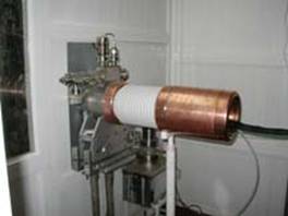
Positron
Source.
The
source is essentially a copy of the Frascati source, which in turn is based on the
SLC source. The source is inline with the electron linac, at the 200 MeV point.
The target is removed when filling the rings with e-. For e+, either of 2
identical targets can be inserted. Just in front of the target is a profile
monitor for adjusting the diameter and position of the incident e- beam. The
flux concentrator is designed to operate at a peak current of 12 kA. The short
capture section is constant gradient, driven by K3 at 15 MeV/m. Two 3-m
sections follow driven by K4 at 20 MeV/m. These sections have a DC solenoid
around them operating at 0.5 T. There is then a 3-m gap. K5 drives 4 3-m
sections, etc. to K16.
After
the beam was restored, Wang showed me an interesting phenomenon: the beam
diameter expaned slowly, then would suddenly collapse with a period of about 1
s. I speculated that this could be the effect of charging up of the ceramic
break in the first toroid due to stray e- from the beam. However,
the expert on these toroids says that in fact the ceramic gaps are all
shielded.
Klystrons.
The
linac has 16 klystrons, 13 with SLED; most are Toshiba E3730A (45 MW), a few
are Thompson, a few SLAC 5045. The e- linac is being upgraded from 1.5 to 1.89
GeV. The energy gain comes from converting to higher power klystrons. Full
demonstration of this new peak energy awaits the upgrading of 3 modulators.
The
positron capture section (a short constant impedance section) has 15 MV/m
gradient. The positrons are first decelerated until the bunch length is
minimized, then accelerated. The acceleration section operates with a 20 MV/m
gradient.
Table 1. Information on gun (from GU).
|
|
Bias |
Ipk |
Pulse width |
|
|
|
(kV) |
(A) |
(ns) |
|
|
Old gun (DC) |
80 |
1 |
2.5 |
|
|
|
100 |
5A |
2.5 |
1988-2004 |
|
New gun (pulsed 3-5 ms) |
150-200 |
10-15 |
1 (2 pulse) |
BEPC II |
Shanghai
Institute for Applied Physics (SINAP) and the
Notes based on visit Nov. 29, 2004, by Jym Clendenin.
1. The 100 MeV linac. This is a fairly standard
S-band (2856 MHz) linac with a DC-biased thermionic gun, pre-buncher, 3-m
injector section in which the first 12 cells vary from 0.75c gradually up to c
(but no separate rf phase or amplitude), followed by 12 additional m of
accelerator, all driven by a single 45 MW Thompson klystron. The first 3-m
section has separate phase and amplitude control at high power. The linac can
operate at 1-50 Hz.
The gun pulser operates in 2 modes. For FEL studies, 1
nC, 1 ns at 25 Hz are required. A second mode can produce 50-140 ns pulses.
There is a lens and then a toroid just after the gun.
The pre-buncher (with 1 solenoid coil) is about 0.5 m from the gun, followed by
the injector accelerator (with 14 solenoid coils). The next accelerator section
has another 14 solenoid coils. Correctors are inside the solenoids. There is no
other steering between the cathode and the end of the injector section. BPM
strip monitors begin at this point also. All the downstream focusing is
symmetrical (quadrupole triplets). At the end of the linac there is a
straight-ahead dump, also a dipole for an energy analyzer followed by a dump.
This linac with the addition of an rf gun will be used
to study the injector for the SSRF. For this it appears to me that better
control of the beam between the gun and the injector section will be necessary
or at least useful: 2-3 corrector/BPM stations. Measuring or at least
monitoring the bunch length after the first section will also be an important
diagnostic.
For the SDUV-FEL, a 1.6-cell rf gun of the BNL design
will be installed. The metal cathode (Cu or Mg) will have a 6 mm radius. The
requirements are: 100-120 MV/m at the cathode at a repetition rate of 25 Hz, e=4-6x10⁻⁶
m, 1 nC, 10 ps. A QE of at least 2x10⁻⁵ hoped for. The gun energy
will be 5-6 MeV.
2. Two smaller linacs. In a second building there are
2 smaller linacs. One has existed for several years, has a standard thermionic
gun, and is used to supply an electron beam for chemistry studies. The second
seems dedicated to rf gun development. The present rf gun has a thermionic
cathode.
3. SSRF. Apparently there is now official approval to
build the light source. It will be a 3rd generation source. The
present decision is to build it in the city to make it more convenient for
users. Operation is not expected until ~2010.
Return to Sources Group Home Page
This page maintained by Jym Clendenin and was last updated 09 December 2004.