 HVS 10/11/00
The issue of wire scanner based emittance measurements has often brought some levels of confusion in regard to the modelling parameters used. The model parameters used are an important part of the result. In this note I try to enumerate, for future reference, the information I have gathered regarding this issue.
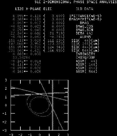
Below I refer to the pictures drawn by SCP for emittance calculation as "frisbee pictures". (they look like frisbees to me)
It is expected as background that the reader is familiar with the notion of reconstructing a transverse phase space ellipse at a given beamline Z location (for these frisbee pictures, the beamline location is that of the first of the group of wires) given a set of beam size measurements whose phase space orientation can be "projected" back to the first wire. This projection needs a model of the transfer function (Rij's) between wires.
The model used is determined (obviously) by the SCP. For a given set of wires, there are generally several models possible. The SCP chooses a model base on it's determination of it's current "twiss mode". Examples of "twiss mode" include SLCe-, PEPe-, SLCe+, FFTBe_, etc. The SCP's choice for "twiss mode" is detemined by the flavor of beam selected (e- or e+) and also the SCP's "machine mode". There are probably other things which influence SCP's decision which I have not uncovered.
Based on the "twiss mode" used, the SCP get's the Rij's necessary to do the phase space reconstruction from the current database model for that "twiss mode". Note for example, that in sector two there is a generally different database model for PEPe- than there is for FFTBe-. Therefore an emittance calculation would generally be different if the different "twiss modes" are used. (The Rij's between wires are generally different for different model modes).
This is all fine so far.
There is another little detail which is important. There is a file, called slcmodlskl:wsopt_emit_model_setup.dat which has some more information which the SCP uses. For each set of wires, and for each "twiss mode", this file lists a set of nominal values used to perform the calculation. For each set of wires, this file specifies (differently for each "twiss mode") a nominal value for beta and alpha at the first wire. These two values, together with the Rij's from the whatever model is used, are what determine how the projection of four size measurements is used to reconstruct a phase space ellipse. This file also contains a nominal emittance value which is used (together with the beta, alpha, and Rij's) to determine the "reference ellipse" shown on the frisbee picture...as well as the reference wire sizes listed in blue text on the frisbee display.