
Maintained by
Matt Boyes &
William Colocho
Modified
Tuesday, 17-Oct-2006 14:05:15 PDT
Description | Save/Restore Configs |
Printing | Advance
Due to temperature dependent hardware drifts, the phase of some PEP II
stations changes diurnally. Power balance feedback loops can work to keep
the relative phase of two given stations constant. The loop uses a given
station as the 'Reference station'. The Feedback then controls the 'base
phase' (L/HRXX:STN:PHASE:CALC.C) of the station under control to keep the
relative power of the two stations at a fixed ratio. These EPICS based
loops can be controlled from the Power Balance Loop EPICS panel.
The following checks are performed before the feedback changes the base phase
of the station under control.
- On Initialization (change of FBCK State), FBCKOut
will be set equal to BasePhase.
- Feedback State needs to be ON, if not FBCK State
will be purple to indicate it is
selected OFF
and the Status will be red
to indicate Feedback is not running.
- Beam current needs be over (user selectable) threshold, if it is not the
Current Threshold interlock will be
red to indicate the problem and the
Status will be red to indicate
Feedback is not running.
- Reference station and station under control needs to be ON_CW, if
this interlock is not true then the Station to Track
select/interlock will be
red to indicate the problem and the
Status will be red to indicate
Feedback is not running.
- Reference station and station under control cannot be the same (HR8-1
cannot Track HR8-1) if this interlock is not true then the Station to
Track select/interlock will be red to
indicate the problem and the Status will be
red to indicate Feedback is not running..
- Measured Power Ratio is assoctiated a alarm status which will turn
yellow or red depending if the Power Ratio Setpoint
and the Measured Power Ratio differ by 5% and 10% respectfully
If the feedback is active, the calculation of the new base phase goes as
follows:
If KlysFWRDPower is greater than (Reference
KlysFWRDPower * Power Ratio* 0.001)
then
FBCKOut = previous
FBCKOut - StepSize
else
FBCKOut = previous
FBCKOut + StepSize
List and display Configs
To sort list Click on Name or Last modified
It is desireable at times to look up Historys of some of the PVs used in this Feedback. The PVs below are in History buffers:
| | Pepii Archiver | SLC History Buffer |
| Feedback Actuator | $(STN):STN:PHASE:CALC.C | $(STN):STN:PHASE:CALC.C |
| Klys Fwd Power | $(STN):KLYSOUTFRWD:POWER | $(STN):KLYSOUTFRWD:POWER |
| Power Ratio Setpoint* | RB00:$(RING):$(STN):AO:RATIO | RB00:LR42:RATIO |
| Klys Fwd Power* | RB00:$(RING):$(STN):AO:STEP | RB00:LR42:STEP |
* NOTE: Pepii Archiver and SLC History Buffer PV names are different!
There are two methods to print the Power Balance display.
- Print Button on the Display
Bring up a printer selection list, preforms a screen grab seconds later and send output to selected printer. This method also corrects orientaion for Elogs.
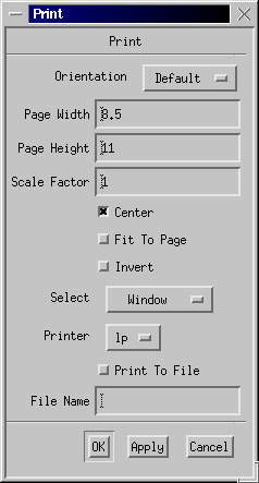
- Middle Mouse Button dialog Print
Bring up the Dialog below. Users are able to select customize
print options.
NOTE: When printing to Elogs, Select "Portrait" Orientation,
so Elogs will not rotate image.
- What to edit in this Application in order to add additional RF Stations
- Items to edit
- db templete file:
PowerBalance_all.template
- Display file: rfb_main.edl
- ChannelWatcher for bumpless reboot
$CD_SOFT/dev/confsys/CW.RB00.?ER
?= Ring
- Config Save/Restore PV List
- Stations added to HER.pvlist and LER.pvlist
/a/mccfs0/u1/pepii/ctrl/rfb00pep00/pvs/makepvslist.script
- Reference Docs
- Database files
- Names
<Appname
> = rfbApp
<LCmicroname> = RB00
<nodename
> = rfb00pep00