Last printed 05/07/99 7:02 AM
South Damping Ring Interlock/Control Upgrade
The South Damping Ring interlocks are now controlled by an Allen-Bradley Small Logic Controller, SLC 500 series. Many of the systems in the SDR are controlled from EPICS which communicates with the SLC 500 controller. This document describes the operational changes made to the SDR control system.
Outline
- Allen-Bradley Controller
- SLC 500 Controller
- Digital Input
- Digital Output
- Analog Input
- Analog Output
- DCM – Scanner
- Station Controller
- Interlocks and System Control
- Cavity tuners
- Pi Cavity
- Klystron
- Gap Voltage Feedback
- VCO control
- Station Phase, S-Band Feedback, and Direct (Flemming) Feedback
- Allen-Bradley Controller
The SLC 500 Control System can run stand alone to operate the damping ring interlock system and control some of the subsystems. The System Controller contains a 2711-B5A5 touch panel with numeric entry keypad, figure 1. EPICS allows remote control of the SLC 500 system through a DCM and Scanner. The SLC 500 Controller in the SDR uses two 1746-A7 seven slot chassis, each with its own 1746-P4 power supply. The profile of the chassis are given in figure 2.
- SLC 500 Controller
The SLC 5/05 CPU has a resident program and runs locally. The processor code is programmed via ladder logic. The integral ethernet port allows programming to be done remotely.
- Digital Input
The 1746-IB32 is a 32 bit digital input module. The signals input are at a +15V to +26V level at 5mA with a common ground. There is a maximum signal delay of 3ms. Two of these modules are used for interlocks and monitoring.
- Digital Output
The 1746-OB32 is a 32 bit output module. The output modules receive 24VDC for the outputs via the station controller. The output modules are rated to operate from 5 to 50VDC with a maximum current of 500mA per point at 30°
C. The maximum output for the module should not exceed 2.0A. Signal delays are 0.1mS for On and 1.0mS for Off.
- Analog Input
The 1746-NI8 is an 8 channel differential analog input module. The modules have 16 bit accuracy and are used to read in ±
10VDC signals.
- Analog Output
The 1746-NO4V is a 4 channel analog output module. The modules have 14 bit resolution with a 2.5mS response time. The output range is ±
10VDC and an overall accuracy drift of ±
54ppm/°
C of full scale.
- DCM – Scanner
The DCM in the SLC 500 system is used to communicate with EPICS via a VXI scanner module in the VXI crate located at DAR2450 in the DR Alcove.
- Station Controller
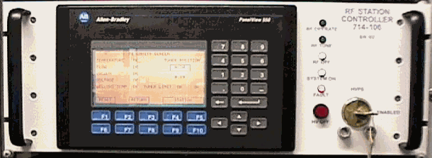
Figure 1 Station Controller
The Station Controller is located above the Allen-Bradley Controller in rack DAR23 in the damping ring alcove. The keylock switch enable for the high voltage power supply is located on the station controller. There is a high voltage off button on the station controller next to the keylock switch. All other control is done through the Allen-Bradley touch panel.
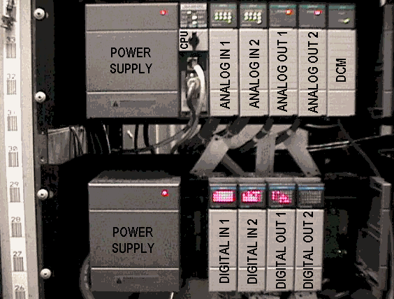
Figure 2 Allen-Bradley SLC-500 Controller located in rack DAR23 in the DR alcove.
- Interlocks and System Control
Note: In this document as well as other places the klystron heater is referred to as filament for historical reasons. The labels focus coil and magnet are used interchangeably to refer to the klystron beam focusing magnet.
All interlock logic is now being done by the SLC 500 system. The interlocks can be reset in the DR alcove from the touch panel or remotely from EPICS. SYSTEM ON/OFF is controlled only from the Station Controller in the DR alcove. FILAMENT On/Off and FOCUS COIL On/Off are controlled by the SLC 500 and are turned on when SYSTEM is on and interlocks are made up. HIGH VOLTAGE ON/OFF and RF OFF/TUNE/OPERATE can be controlled from the Station Controller or through EPICS. There is a timer to turn off High Voltage if the RF is off for 20 minutes. The following is a list of interlocks and the function they prohibit.
Function Interlocks
SYSTEM NONE
FILAMENT SYSTEM ON : RF Cabinet Air : Klystron Installed : Power Upper limit
FOCUS COIL SYSTEM ON : Magnet coolant flow : Magnet coolant temperature
Current Upper limit
HIGH VOLTAGE SYSTEM ON
Power Supply Cabinet : Power Supply Door and Ground Hook : Heater under current
Heater time out : Magnet over current : Magnet under current : Klystron Collector Coolant Flow Klystron Collector Over Temp. : Klystron Collector Over Current : Klystron Beam Over Voltage
Klystron Body Over Current : Klystron Body Coolant Flow : Klystron Body Coolant Temperature
RF Cabinet HV Access : High Voltage Supply Smoke Detector : High Voltage Beam Over Current Heat Exchanger Flow/ Overflow : High Voltage Supply SCR Temp : Klystron Installed
RF ON HIGH VOLTAGE ON
Waveguide to Coax Cooling Flow : Klystron Arc Detector : Cavity 591 Vacuum
Cavity 811 Vacuum : Waveguide Tee Load Flow : Waveguide Air : Vacuum Chamber LCW Flow
Cavity 591 LCW Flow #1 : Cavity 591 LCW Flow #2 : Cavity 591 LCW Flow #3
Cavity 811 LCW Flow #1 : Cavity 811 LCW Flow #2 : Cavity 811 LCW Flow #3
Cavity 591 Tuner Bellows Temp. : Cavity 811 Tuner Bellows Temp. : Cavity 591 LCW Over Temp.
Cavity 811 LCW Over Temp. : Cavity 591 Body Over Temp. : Cavity 811 Body Over Temp.
P
Mode Cavity Over Voltage : P
Mode Cavity Temperature : P
Mode Cavity Flow
P
Mode Cavity Vacuum : Reflected Power
Several of the interlocks are displayed on the EPICS Interlock panel, figure 4, which is entered from the main SDR EPICS control page, figure 3. The interlock Reset can be activated from both panels. The Interlock panel shows all the interlocks for the High Voltage Power Supply, HVPS, the filament and the focus coil.
From the South Damping Ring RF Main Page, pages for Interlocks, Klystron, Cavity A, Cavity B, Pi Cavity, and Diagnostics can be reached. The Local/Remote status is displayed on this page. Local/Remote control can only be changed at the Station Controller in the DR Alcove. The Local/Remote function allows the ring to be controlled from either the local Station Controller or Remotely form EPICS. The High Voltage Power Supply, HVPS, can be turned on and off. The status of the HVPS is displayed next to the On and Off buttons. The RF mode can be Off, Tune, or Operate and must be turned on in sequence. Tune mode allows the tuners time to adjust at a lower RF power level before high power is output in operate mode. There is a 5 second delay from the time Tune mode is entered to the time Operate mode can be entered.
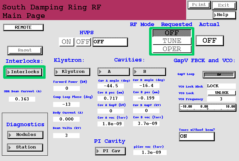
Figure 3. South Damping Ring RF Main Page - EPICS control.
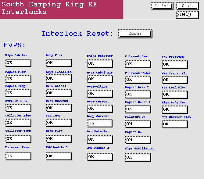
Figure 4. SDR EPICS control panel - Interlock Page.
- Cavity Tuners
The cavity tuners have been changed and are now controlled from the SLC 500 System. They can be operated from the local Station Controller or remotely from EPICS. When in local control, all parameters used in tuner operation are those entered from the local Station Controller. When in Remote control all parameters used in tuner operation are those entered through EPICS. The EPICS set of parameters and the Station Controller set of parameters are separate and are not effected by each other. The EPICS Cavity A control panel is shown in figure 5. Cavity B panel is similar.
The Reset button on the panel will reset all interlocks. The interlock status is listed in the Interlocks column. Any one of these interlock faults will shut off the RF.
The Cavity A gap voltage and Vacuum are displayed for reference.
The Tuner Control button selects Automatic or Manual mode of operation. In Automatic mode the cavity tuning angle is adjusted to the selected angle. The actual angle is displayed just above the selected angle. In Manual mode the cavity tuner position is adjusted to the selected tuner position. The actual tuner position is displayed just above the selected position.

Figure 5. EPICS Cavity A Control Panel.
The functionality remains the same as before with two additions. There now exist soft limits which can be set by an operator. The soft limits work only in automatic mode where the tuners are controlled by phase. The position of the desired upper and lower limit is entered in the Tuner Upper Limit SW and Tuner Lower Limit SW boxes. When in automatic mode the tuners will not be allowed to move beyond these limits. This reduces the tuner range and can be used to keep the tuners from wandering off or from entering areas where higher order mode heating is a problem. The electrical limit switches will always stop the tuner motion when reached. The state of the electrical limit switches are given by the Upper Limit and Lower Limit status indicators.
The second addition is the setting of the Tune with Beam Only current threshold. There is an uncalibrated Beam Current Monitor reading this is used to determine where to set the threshold for Tune with Beam Only. The Beam Current Seen is an uncalibrated diode detected signal from a BPM. If Tunes without beam? is in BEAM state, the SLC controller will only allow tuner motion if Beam Current Seen is above Beam Current Thresh. Motion is stopped by not allowing upper or lower motion. This can be seen by both the Upper Stop and Lower Stop displays being in a Stop state at the same time.
Cavity RF is displayed. While in Automatic mode the tuner will not move if RF is not present.
- Pi Cavity
The Pi Cavity tuner is now controlled by the SLC 500 from the station Controller or through EPICS. The EPICS control panel for the Pi Cavity is shown in figure 6. The five interlocks shown on the control panel are Pi Cavity Water, Pi Cavity temp, Pi Cavity Vacuum, Pi Cavity Power, and Pi Bellows Temp. If any one of these interlocks are faulted the RF will be turned off. The Pi Cavity vacuum and power are displayed for reference. The Pi Cavity tuner is adjusted by changing the tuner position. The actual position is displayed above the entry bar for the desired position. The Upper Limit and Lower Limit display the status of the electrical limit switches. Up Motion and Down Motion status show if the controller will allow up or down motion. The only item to inhibit up or down motion in the electrical limit switch and therefore one would expect to see Upper Limit and Up Motion to change state together. Likewise the Lower Limit and Down Motion should also change states together.

Figure 6. SDR Pi Cavity EPICS panel.
- Klystron
The klystron systems controlled and monitored by the SLC 500 are as follows:
- Monitoring and interlocking of various analog signals.
- Interlocking of digital signals.
- Control and monitoring of the klystron phase or Comp. Loop.
The South Damping Ring RF Klystron EPICS page is shown in figure 7.
The analog signals are displayed along with their interlock status. The filament (Heater) under limit must be maintained for 5 minutes before the Filament Timeout interlock will make up. This allows the heater to bring the cathode up to temperature before extracting electrons from it.
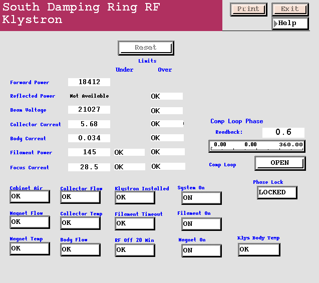
Figure 7. SDR Klystron EPICS panel.
Although not controlled from EPICS, the status for System On, Filament On, and Magnet On are displayed. The interlocks which are associated with the klystron sum are part of the interlocks which keep off the klystron high voltage power supply and are displayed on this panel.
It was observed in the past that when the direct feedback loop remained on and RF was off, that settings of phase and gain of the direct loop caused the klystron to oscillate. To prevent damage of the high power RF and ring components, interlock logic has been added to check if RF is present at the cavity inputs when the RF is in an off state. If RF is detected, the klystron high voltage is turned off. This interlock is labeled Kly Osc.
The klystron phase loop or comp loop is now controlled from the EPICS klystron panel. This is a 100Hz feedback loop which stabilizes the phase from down stream of station phase to the cavity output phase. Use of this loop reduces drifts in injection phase. The readback is the actual phase reading around the loop which is held about zero when the loop is locked. The phase entry allows an offset to be entered into the loop to get the phase of the loop in a range about zero which will allow locking. The Comp Loop button opens (unlocks) and closes (locks) the loop. The label on the button, open or close, is the action that occurs if the button is pressed. If the loop is closed the button will read open and will open the loop if pressed. The phase lock indication gives the status of the loop.
To calibrate the loop the following steps are preformed with RF on.
- Open (unlock) the loop.
- Move the phase until the readback is about zero ±
10°
.
- Close (lock) the loop.
- Gap Voltage Feedback
The control voltages, set points, for the gap voltage min, max, and intermediate are still entered from the SCP. The tune/operate function and loop open/close function of the gap voltage controller are now controlled by the SLC 500 system. The tune/operate function is performed as the RF mode is changed. The GapV Loop Off/On (Open/Close) control is found on the Main Page, see figure 3. If the loop is closed the button will read Off and pressing the button will open, turn off, the feedback loop. With the loop off there is no feedback to regulate the gap voltage.
- VCO control
The VCO is now controlled from the Main Page in EPICS, see figure 3. The VCO Lock button will perform the operation listed on the button. If the button reads lock, pressing the button will lock the VCO. The actual status of the VCO, lock/unlock, is displayed in the VCO Lock Rbck box. The VCO frequency can be changed by moving the VCO frequency adjustment. If the frequency adjustment is changed while the VCO is locked, the VCO may become unlocked. The VCO should always be unlocked when making this adjustment. The frequency readback for the VCO not yet available in EPICS and can be found on the VCO panel on the SCP.
If the VCO will not lock, adjustment of the frequency control may be necessary. To do this first unlock the VCO. Then adjust the control frequency until the frequency readback,, currently from the SCP, reads 714000000 ±
20000Hz.
- Station Phase, S-Band Feedback, and Direct (Flemming) Feedback
The Station Phase, S-Band Feedback, and Direct (Flemming) Feedback are unchanged. All controls and monitoring remain as they were from the SCP.
South Damping Ring Cross Connects
Rack 25 Top

Rack 25 Bottom

Rack 24
North Damping Ring Cross Connects
Rack 19 Top

Rack 19 Bottom
Rack 18