
GLAST LAT Performance |
The top-level science performance requirements for the LAT are given in Table 1 of the Science Requirements Document. The resulting performance is governed primarily by three things
- LAT hardware design
- Event reconstruction algorithms
- Background selections and event quality selections
Thus, although hardware integration and testing are now complete, as the event selection algorithms are optimized the performance must be updated. In other words, there is not a single, intrinsic, set of science performance parameters, but rather results of choices. These are based on detailed Monte Carlo simulations, along with beam tests and ground-level muon tests to check the characterization in the simulation. Standard sets of analysis choices, and their resulting performance characteristics, will be maintained by the LAT team. Earlier performance descriptions are archived here: v2 and v3.
Note that a number of significant improvements are underway, particularly in the background rejection analysis. The performance summarized below is the result of studies for the LAT Service Challenge in 2007, in preparation for flight data analysis. Improvements will be published soon and prior to the GLAST launch.
A result of the analysis is the production of full instrument response functions (IRFs), describing the performance as a function of photon energy, incidence angle, conversion point within the instrument, and other important parameters. The plots below represent the work of many people on the LAT team.
A few important caveats:
- The background rejection analysis is done in bands of energy, resulting in the wiggles; these are under study.
- Starting from the front of the instrument, the LAT tracker (TKR) has 12 layers of 3% r.l. tungsten converters (THIN or FRONT section), followed by 4 layers of 18% r.l. tungsten converters (THICK or BACK section). These sections have intrinsically different PSF due to multiple scattering, and the performance plots are presented for both of these sections.
Point Spread Function, Energy Resolution and Effective Area
The following graphs depict the current estimate for the PSF and effective area performance.

- top left: 68% containment of the PSF (eps version)
- top right: relative effective area vs photon true angle of incidence for 10 GeV photons
FOV is defined as the integral of effective area over solid angle divided by on-axis
effective area (eps version).
- bottom left: on-axis effective area, after all selections (eps version)
- bottom right: 68% containment of the PSF vs photon incoming angle (eps version)
The energy dispersion performance is shown below.
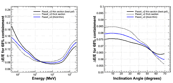
- left: 68% containment of the energy dispersion vs incoming photon energy
- right: 68& containment of the energy dispersion vs incoming photon direction for a 10GeV photon
Point Source Sensitivity Plots
Using the above instrument performance characterization, we have produced additional plots related to point source sensitivity.
The first is a single-energy-bin sensitivity plot, showing the 5-sigma sensitivity to a high-latitude source whose spectrum is integrated over 1/4 decade in energy centered on the energy shown on the horizontal axis. Sensitivity is defined as the flux such that the log of the expected likelihood ratio for detection is 25/2 (or 5 sigma in the Gaussian case) and at least 5 photons. Thus, this plot shows the point source sensitivity using only the photons in each energy bin separately. The assumptions are:
- one calendar year all-sky survey (including effects of the SAA and deadtime)
- diffuse background flux 1.5x10⁻⁵/cm2/s/sr (E>100 MeV); spectral index -2.1
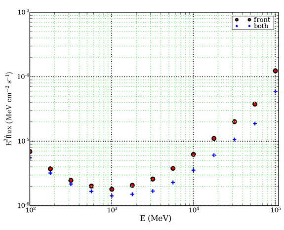
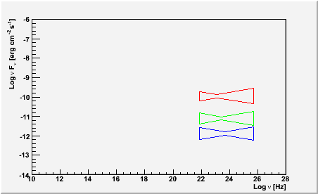
The point source sensitivity using the information in all energy bins is much better than the individual energy bin sensitivities above. We therefore provide the integral sensitivity measures in two ways.
First the bowtie plot, which shows the minimum needed for a 20% determination of the flux after a one-day, one-month, and one-year of operation in all-sky survey for a 1/E2 source. The resulting significance at each of these levels is about 8-sigma; the spectral index is determined to about 6%; and the bowtie shape indicates the energy range that contributes the most to the sensitivity. To make a measurement at that level or better, a flat spectral energy density curve must lie above the axis of the bowtie.
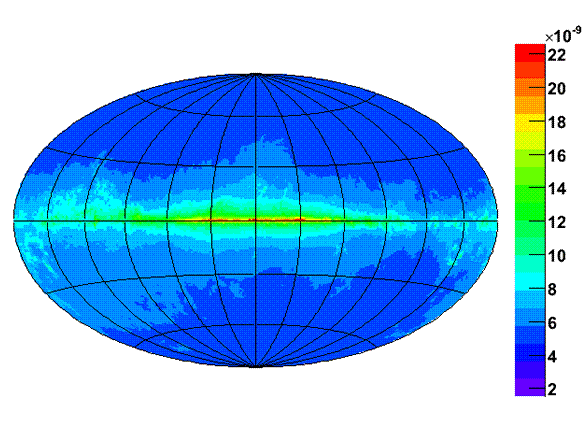
There are significant variations of the sensitivity in the sky due to the spatial structure in the diffuse galactic gamma-ray background. These are summarized in the map below, which shows the sensitivity across the sky in Galactic coordinates.
Finally, experiments are often compared using an integral sensitivity plot (5-sigma sensitivity for E>E0), assuming a 1/E2 spectrum source at high latitude. We show here an update for the GLAST LAT:

Gamma-ray Bursts Sensitivity
An estimator for the Localization power as a function of the fluence is plotted in the graph below.
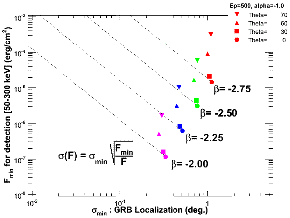
Each marker corresponds to a different inclination angle, and a different high energy spectral index, and represents the minimum fluence which corresponds to a detection (y-axis) vs the 68% localization accuracy. The dotted lines are the result of the formula on the canvas and allows computation of the localization at a given fluence (for normal incidence).
If there is any additional information you would find useful to have posted on this page, please contact S. Ritz ![]() and/or the LAT Analysis Coordinator, Julie Mc Enery
and/or the LAT Analysis Coordinator, Julie Mc Enery ![]() .
.
Useful links:
- LAT Home Page
- LAT Design, Development, and Operations Page
- GBM Home Page
- GLAST Mission
- GLAST Users Committee
updated 14/8/2007, maintained by Steve Ritz